Flanged Beams — T-Beams & L-Beams in Flexure (IS 456:2000)
In this chapter (3 topics)
On this page
- 1. Introduction & Structural Action of Flanged Beams
- Key Engineering Advantages of Flanged Beams:
- 2. Shear Lag Phenomenon & Effective Flange Width (bf)
- 2.1 The Concept of Effective Flange Width (bf)
- 2.2 IS 456:2000 Codified Formulas for bf (Clause 23.1.2)
- 3. Case 1: Neutral Axis Lies Within the Flange (xu ≤ Df)
- 3.1 Mathematical Formulations for Case 1
- 4. Case 2A: Neutral Axis in Web with Shallow Flange (xu > Df and Df ≤ frac37 xu)
- 4.1 Physical Criterion for Shallow Flange
- 4.2 Compressive Forces & Neutral Axis Formulation
- 4.3 Moment of Resistance (Mu)
- 5. Case 2B: Neutral Axis in Web with Deep Flange (xu > Df and Df > frac37 xu)
- 5.1 The IS 456 Annex G Equivalent Thickness Factor (yf)
- 5.2 Compressive Equilibrium & Neutral Axis Depth (xu)
- 5.3 Moment of Resistance (Mu)
- 5.4 Limiting Moment of Resistance (Mu,lim) for Deep Flanged Beams
- 6. Inverted T-Beam Action & Negative Moment Behavior at Continuous Supports
- 7. Systematic Analysis Algorithm for Flanged Beams
- 8. Worked Numerical Examples
- Problem 1: Analysis of T-Beam with Neutral Axis in Flange (Case 1)
- Problem 2: Analysis of T-Beam with NA in Web — Shallow Flange (Case 2A)
- Problem 3: Analysis of T-Beam with NA in Web — Deep Flange (Case 2B with yf)
- 9. Common Misconceptions & Exam Pitfalls
- 10. Comparative Summary & Master Formula Sheet
- Master Formulations for Flanged Beams
- 11. Practice Questions & Competitive Examination Problems
- Question 1 (GATE CE — 1 Mark)
- Question 2 (UPSC ESE — Objective)
- Question 3 (SSC JE — Technical)
- Question 4 (State AE — Analytical)
- Question 5 (GATE CE — 2 Marks)
- Question 6 (UPSC ESE — Conventional)
- 12. References & Code Standards
1. Introduction & Structural Action of Flanged Beams
In typical cast-in-place reinforced concrete construction, floor slabs and supporting beams are cast monolithically. Under positive (sagging) bending moments—such as in the middle of a simply supported or continuous span—the top fibers of the beam are in compression while the bottom fibers are in tension.
Because the slab is cast integrally with the beam, a portion of the slab on either side of the beam web acts as a wide compression flange, while the narrow beam below the slab functions as the web (or rib) to resist shear and house the longitudinal tension reinforcement.
- T-Beams: Formed at interior bays where the slab extends continuously on both sides of the web.
- L-Beams (Inverted L / Spandrel Beams): Formed at exterior perimeter edges where the slab extends on only one side of the web.
+----------------------------------------------------------------------------------------------------+
|                                 MONOLITHIC BEAM-SLAB FLOOR SYSTEM                                  |
+----------------------------------------------------------------------------------------------------+
|                                                                                                    |
|    |<-- b1/2 -->|                   |<------ b ------>|                   |<-- b2/2 -->|           |
|    +------------+-------------------+-----------------+-------------------+------------+  ---      |
|    |            |                   |                 |                   |            |   | Df    |
|    |            |      SLAB         |   TOP FLANGE    |      SLAB         |            |   |       |
|    +-----+------+-------------------+--------+--------+-------------------+------+-----+  ---      |
|          |                                   |                                   |                 |
|          | L-BEAM                            | T-BEAM                            | L-BEAM          |
|          | (Perimeter)                       | (Interior)                        | (Perimeter)     |
|          |                                   |                                   |                 |
|          |<--bw-->|                          |<--bw-->|                          |<--bw-->|        |
|          +--------+                          +--------+                          +--------+        |
+----------------------------------------------------------------------------------------------------+
Key Engineering Advantages of Flanged Beams:
- Massive Compressive Capacity: The wide top slab provides an immense compression area, ensuring that singly reinforced flanged beams rarely crush in compression.
- Material Economy: Concrete in the cracked tension zone is eliminated, significantly reducing the dead weight of the floor system compared to a solid rectangular beam of width .
- Enhanced Deflection Rigidity: Flanged beams exhibit substantial flexural stiffness (), reducing service load deflections across long spans.
2. Shear Lag Phenomenon & Effective Flange Width ()
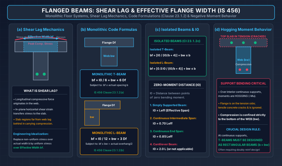
In elementary beam theory, bending normal stress is assumed uniform across the entire width of a cross-section. However, in wide-flanged RC beams, compressive forces are introduced into the slab exclusively through the beam web. The compressive stress is transmitted outward into the slab flange via in-plane horizontal shear stresses.
Because the slab possesses finite in-plane shear stiffness, the longitudinal compressive strain lags behind with increasing distance from the web. Consequently:
- Compressive stress is maximum directly over the web.
- Compressive stress decays non-linearly toward the outer edges of the slab overhang.
This phenomenon is known as Shear Lag.
2.1 The Concept of Effective Flange Width ()
To avoid complex 3D non-linear stress integration in practical engineering, the actual non-uniform compressive stress profile across the full slab width () is replaced by an idealized, equivalent uniform compressive stress acting over a reduced width called the Effective Flange Width ():
2.2 IS 456:2000 Codified Formulas for (Clause 23.1.2)
1. Monolithic / Continuous T-Beams (Clause 23.1.2 a):
2. Monolithic / Continuous L-Beams (Clause 23.1.2 b):
3. Isolated T-Beams (Clause 23.1.2 c):
For beams where the flange is not part of a continuous floor slab (e.g., precast girders, isolated footbridges):
4. Isolated L-Beams (Clause 23.1.2 c):
Where:
- : Effective width of flange ().
- : Width of web / rib ().
- : Thickness of flange / slab depth ().
- : Actual width of the flange (center-to-center distance between adjacent bays).
- : Distance between points of zero bending moment along the span:
- For Simply Supported Beams: (effective span).
- For Continuous Intermediate Spans: .
- For Continuous End Spans: .
3. Case 1: Neutral Axis Lies Within the Flange ()
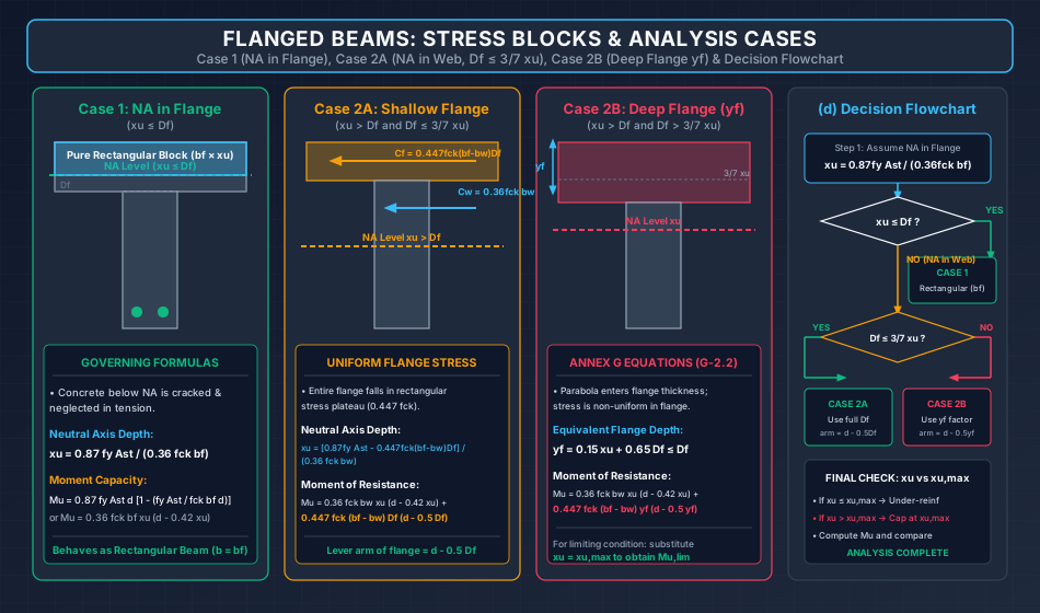
When the amount of tension reinforcement is moderate or the effective flange width is large, the neutral axis falls completely within the slab flange ().
Because concrete below the neutral axis is in tension and completely neglected in flexural calculations, the concrete compression zone is a simple rectangle of width and depth . The overhangs outside the web below the neutral axis are already cracked, so whether they exist or not has zero effect on the internal stress block!
   <------------------------ bf ------------------------>
   +----------------------------------------------------+  ---
   |             COMPRESSION ZONE (CONCRETE)            |   |
   |              Uniform Width = bf                    |   | xu <= Df
---+----------------------------------------------------+---+--- NA (eps = 0)
   |  . . . . . . . . . . . . . . . . . . . . . . . . . |   | Df
   +--------------------+          +--------------------+  ---
                        |          |
                        |   WEB    |
                        |  CRACKED |
                        | (O)  (O) |
                        |<-- bw -->|
3.1 Mathematical Formulations for Case 1
-
Actual Neutral Axis Depth ():
-
Verification Condition: Check if . If true, Case 1 is confirmed.
-
Limiting Neutral Axis Depth ():
-
Moment of Resistance ():
- For an Under-Reinforced Section ():
- For a Balanced Section ():
4. Case 2A: Neutral Axis in Web with Shallow Flange ( and )
When tension reinforcement is heavy, the neutral axis crosses the flange-web junction and enters the web (). The compression zone now forms a T-shaped area.
To evaluate capacity, the T-shaped compression zone is divided into two distinct components:
- The Web Component: A rectangular column of concrete of width and depth .
- The Flange Overhang Component: Two symmetrical flange projections of combined width and thickness .
4.1 Physical Criterion for Shallow Flange
In RCC-01-03, we proved that the IS 456 parabolic-rectangular stress block maintains a constant uniform stress of from the top fiber down to depth .
Therefore, when:
the entire thickness of the flange overhang falls within the constant rectangular stress plateau! The compressive stress across the entire flange overhang is uniform and equal to .
4.2 Compressive Forces & Neutral Axis Formulation
- Web Compressive Force (): acting at depth from the top fiber (lever arm ).
- Flange Overhang Compressive Force (): acting at the midthickness of the flange (lever arm ).
Equating total compression to total tension ():
Solving for the Actual Neutral Axis Depth ():
4.3 Moment of Resistance ()
Taking moments of internal compressive forces about the tension reinforcement:
5. Case 2B: Neutral Axis in Web with Deep Flange ( and )
When the flange is relatively thick compared to the neutral axis depth ():
- The upper portion of the flange overhang (down to ) experiences uniform stress .
- The lower portion of the flange overhang (from down to ) falls into the parabolic stress region, where stress drops parabolically toward the neutral axis.
5.1 The IS 456 Annex G Equivalent Thickness Factor ()
To avoid integrating parabolic stress over the flange overhangs, IS 456:2000 Clause G-2.2.1 replaces the true non-uniform stress profile over depth with an equivalent uniform stress block of magnitude acting over an Equivalent Flange Depth ():
The flange overhang compressive force is then:
acting at centroid depth from the top fiber (lever arm ).
5.2 Compressive Equilibrium & Neutral Axis Depth ()
Equating :
Rearranging to solve explicitly for :
5.3 Moment of Resistance ()
5.4 Limiting Moment of Resistance () for Deep Flanged Beams
When :
6. Inverted T-Beam Action & Negative Moment Behavior at Continuous Supports
One of the most vital practical concepts in structural concrete design concerns the behavior of continuous flanged beams over interior columns and continuous supports:
- Moment Reversal (Hogging Bending Moments): Over interior supports, continuous beams experience negative bending moments (tension at the top, compression at the bottom).
- Top Flange in Tension: The wide top slab flange is situated on the tension side. Since concrete in tension micro-cracks and is neglected in strength calculations, the wide flange contributes ZERO compressive resistance!
- Compression Confined to Narrow Web: Compressive stress is resisted entirely by the bottom of the beam, which has a narrow width of only .
[!IMPORTANT] GOVERNING STRUCTURAL RULE (IS 456 Clause 23.1.1):
At continuous supports subjected to negative (hogging) bending moments, T-beams and L-beams MUST be designed as RECTANGULAR BEAMS of width !
Because is narrow, the section frequently becomes over-reinforced unless its depth is very large; hence, flanged beams over continuous supports are almost universally designed as doubly reinforced rectangular sections () with compression steel placed in the bottom of the web.
7. Systematic Analysis Algorithm for Flanged Beams
+----------------------------------------------------------------------------------------------------+
|                                    FLANGED BEAM ANALYSIS ALGORITHM                                 |
+----------------------------------------------------------------------------------------------------+
|                                                                                                    |
|   Step 1: Compute Effective Flange Width (bf) per IS 456 Clause 23.1.2:                            |
|           bf = l0/6 + bw + 6 Df  (for T-beam)  or  l0/12 + bw + 3 Df  (for L-beam)                |
|                                                                                                    |
|   Step 2: Trial Neutral Axis Calculation (Assume NA lies within Flange):                           |
|           xu,trial = (0.87 * fy * Ast) / (0.36 * fck * bf)                                         |
|                                                                                                    |
|   Step 3: Classify Neutral Axis Position:                                                          |
|           - IF xu,trial <= Df --> [CASE 1: NA IN FLANGE]                                           |
|             Adopt xu = xu,trial. Check xu <= xu,max.                                               |
|             Mu = 0.87 * fy * Ast * d * [1 - (fy * Ast) / (fck * bf * d)]                          |
|                                                                                                    |
|           - IF xu,trial > Df  --> [CASE 2: NA IN WEB]                                              |
|             Proceed to Step 4.                                                                     |
|                                                                                                    |
|   Step 4: Sub-classify Flange Depth (Check Df vs 3/7 xu):                                          |
|           - Assume Df <= 3/7 xu [CASE 2A: SHALLOW FLANGE]:                                         |
|             Compute Cf = 0.447 * fck * (bf - bw) * Df                                              |
|             Compute xu = [0.87 * fy * Ast - Cf] / (0.36 * fck * bw)                                 |
|             Verify if Df <= (3/7) * xu. If verified, Case 2A holds:                                |
|             Mu = 0.36*fck*bw*xu*(d - 0.42*xu) + Cf*(d - 0.5*Df)                                    |
|                                                                                                    |
|           - If Df > (3/7) * xu [CASE 2B: DEEP FLANGE]:                                             |
|             Compute yf = 0.15 * xu + 0.65 * Df                                                     |
|             Solve for xu using equivalent yf equation.                                             |
|             Compute Cf = 0.447 * fck * (bf - bw) * yf                                              |
|             Mu = 0.36*fck*bw*xu*(d - 0.42*xu) + Cf*(d - 0.5*yf)                                    |
|                                                                                                    |
|   Step 5: Cap Moment Capacity if xu > xu,max:                                                      |
|           If xu > xu,max, cap at Mu,lim using xu,max in place of xu.                               |
+----------------------------------------------------------------------------------------------------+
8. Worked Numerical Examples
Problem 1: Analysis of T-Beam with Neutral Axis in Flange (Case 1)
Problem Statement:
An interior simply supported T-beam has an effective flange width , flange thickness , web width , and effective depth . Concrete grade is M20 () and steel grade is Fe 415 (). The tension reinforcement consists of bars of diameter ().
- Determine the actual depth of the neutral axis ().
- Verify whether the neutral axis lies in the flange or web.
- Calculate the ultimate factored moment of resistance ().
Step-by-Step Solution:
Part 1: Trial Neutral Axis in Flange Assume neutral axis lies within the flange ():
Part 2: Location Verification & Section Classification
- Since , the assumption is verified: NA lies within the flange (Case 1).
- Limiting neutral axis depth for Fe 415:
- Since , the section is UNDER-REINFORCED.
Part 3: Ultimate Moment of Resistance () The beam behaves as a rectangular section of width :
(Using lever arm method: ).
Problem 2: Analysis of T-Beam with NA in Web — Shallow Flange (Case 2A)
Problem Statement:
A T-beam has , , , and flange depth . Concrete grade is M20 () and steel grade is Fe 415 (). The tension reinforcement consists of bars of diameter (). Compute the actual neutral axis depth and the ultimate moment of resistance.
Step-by-Step Solution:
Part 1: Check if NA is in Flange
Therefore, the neutral axis lies in the web (Case 2).
Part 2: Check Shallow vs Deep Flange Condition () Assume the flange is shallow ():
- Flange overhang compressive force:
- Compute from web equilibrium:
- Check condition: Since , the shallow flange assumption (Case 2A) is strictly verified.
- Check limiting neutral axis: Since , the section is under-reinforced.
Part 3: Ultimate Moment of Resistance ()
- Moment from web component:
- Moment from flange overhang component:
- Total Ultimate Moment Capacity ():
Problem 3: Analysis of T-Beam with NA in Web — Deep Flange (Case 2B with )
Problem Statement:
An isolated T-beam girder has , , , and flange thickness . Concrete grade is M25 () and steel grade is Fe 500 (). Tension steel area provided is . Determine the neutral axis depth using the IS 456 Annex G formulation and calculate the ultimate moment capacity.
Step-by-Step Solution:
Part 1: Check NA Position
The neutral axis extends slightly below the flange into the web.
Notice that .
Hence, the flange is DEEP (), requiring the formulation (Case 2B).
Part 2: Formulation with Equivalent Flange Depth Per IS 456 Clause G-2.2.1:
Axial equilibrium:
- Verify :
- Limiting depth of neutral axis for Fe 500: Since , the section is under-reinforced.
Part 3: Ultimate Moment of Resistance ()
- Web component:
- Flange overhang component:
- Total Ultimate Moment Capacity ():
9. Common Misconceptions & Exam Pitfalls
[!WARNING] Pitfall 1: Using Effective Flange Width () in Continuous Support Hogging Bending
Students frequently design the support section of a continuous T-beam using . Over interior supports, negative bending moments induce tension in the slab; concrete cracks and is neglected. The beam must strictly be analyzed as a rectangular beam of width .
[!WARNING] Pitfall 2: Forgetting to Check whether when NA is in Web
In many competitive exam problems where , students erroneously use in the moment equation without verifying whether . If , the equivalent depth must be used. Omitting causes significant numerical errors.
[!CAUTION] Pitfall 3: Neglecting the Code Upper Bound on
The codified formula can sometimes evaluate to a number greater than the actual center-to-center bay spacing . Remember that is always capped at the actual physical spacing .
[!IMPORTANT] Pitfall 4: Misapplying the Isolated Beam Formula
The formula for isolated T-beams () is fundamentally different from the continuous beam formula. Be careful to check whether the problem specifies an "isolated" girder or a "monolithic floor slab" beam.
10. Comparative Summary & Master Formula Sheet
Master Formulations for Flanged Beams
| Parameter | Governing Mathematical Formula | Remarks / Code Reference |
|---|---|---|
| Continuous T-Beam | IS 456 Clause 23.1.2(a) | |
| Continuous L-Beam | IS 456 Clause 23.1.2(b) | |
| Isolated T-Beam | IS 456 Clause 23.1.2(c) | |
| Zero Moment Distance | (Simply Supported) | (Continuous) | Effective inflection length |
| Case 1 NA () | Rectangular beam of width | |
| Case 1 Moment () | Rectangular beam formula | |
| Case 2A NA () | Uniform flange stress block | |
| Case 2A Moment () | Lever arms: and | |
| Equivalent Flange Depth () | IS 456 Annex G Eq. G-2.2.1 | |
| Case 2B Moment () | Deep flange with | |
| Support Section (Hogging) | (Top flange in tension ignored) | Designed as rectangular beam () |
11. Practice Questions & Competitive Examination Problems
Question 1 (GATE CE — 1 Mark)
A monolithic reinforced concrete floor system has a continuous T-beam with effective span , web width , and slab depth . If the actual center-to-center distance between beams is , the effective flange width of an intermediate continuous span as per IS 456:2000 is:
- (A)
- (B)
- (C)
- (D)
Answer: (A)
Explanation: For intermediate continuous span, .
.
Question 2 (UPSC ESE — Objective)
In a reinforced concrete T-beam subjected to sagging bending moments, if the depth of the neutral axis is less than the flange thickness , the section is analyzed as:
- (A) A rectangular beam of width equal to web width
- (B) A rectangular beam of width equal to effective flange width
- (C) A flanged section using the equivalent flange thickness
- (D) A doubly reinforced section
Answer: (B)
Explanation: Concrete below the neutral axis is in tension and neglected; hence the compressive zone is a pure rectangle of width and depth .
Question 3 (SSC JE — Technical)
For an isolated T-beam with effective span , actual flange width , and web width , the effective flange width as per IS 456:2000 is:
- (A)
- (B)
- (C)
- (D)
Answer: (A)
Explanation: .
Question 4 (State AE — Analytical)
In the limit state analysis of a flanged beam having and , the equivalent depth of flange specified by IS 456:2000 Annex G is:
- (A)
- (B)
- (C)
- (D)
Answer: (B)
Explanation: Clause G-2.2.1 specifies .
Question 5 (GATE CE — 2 Marks)
At the interior support of a continuous reinforced concrete T-beam, the cross-section is subjected to a factored hogging moment of . The beam dimensions are . Concrete grade is M20 () and steel is Fe 415 (). The limiting moment of resistance () available from the concrete in compression at this support is:
- (A)
- (B)
- (C)
- (D)
Answer: (B)
Explanation: Under hogging moment, the top flange is in tension and ignored; compression is resisted strictly by the web ().
.
Question 6 (UPSC ESE — Conventional)
Derive the expression for the ultimate moment of resistance of a T-beam when the neutral axis lies in the web and the flange is shallow ().
Answer Summary: Decompose the compression zone into a web rectangle () and flange overhangs []. The web force is acting at lever arm . Because , the flange overhangs fall entirely in the uniform stress plateau , giving force acting at lever arm . Summing moments: .
12. References & Code Standards
- IS 456:2000 (Reaffirmed 2021): Plain and Reinforced Concrete — Code of Practice, Section 3 (Clause 23: General Design Considerations, Clause 23.1.2: Effective Flange Width, Annex G: Clause G-2: Flanged Sections).
- SP:16 (1980): Design Aids for Reinforced Concrete to IS: 456-1978, Bureau of Indian Standards, New Delhi.
- Pillai, S. U., & Menon, D. (2021): Reinforced Concrete Design, 4th Edition, McGraw-Hill Education, India.
- Varghese, P. C. (2009): Limit State Design of Reinforced Concrete, 2nd Edition, PHI Learning Pvt. Ltd., New Delhi.
- Jain, A. K. (2012): Reinforced Concrete: Limit State Design, 7th Edition, Nem Chand & Bros, Roorkee.