Short Columns under Axial Compression
In this chapter (4 topics)
On this page
- 1. Introduction & Slenderness Classification
- 1.1 Statutory Slenderness Ratio Criteria (Clause 25.1.2)
- 2. Minimum Eccentricity Formulation (emin) — Clause 25.4
- 3. Axial Load Capacity of Short Tied Columns (Clause 39.3)
- 3.1 Derivation & Physical Meaning of Coefficients 0.40 and 0.67
- 4. Helically Reinforced Columns (Clause 39.4)
- 4.1 Statutory 5% Strength Enhancement (Clause 39.4)
- 4.2 Statutory Confinement Ratio Condition (Clause 39.4.1)
- 4.3 Codal Pitch Limits for Spiral Reinforcement (Clause 26.5.3.2d)
- 5. Codal Reinforcement Rules for Columns (Clause 26.5.3)
- 5.1 Longitudinal Reinforcement (Clause 26.5.3.1)
- 5.2 Transverse Reinforcement (Lateral Ties) — Clause 26.5.3.2
- 6. Engineering Diagrams & Detailing Anatomy
- Diagram 1: Short Column Axial Capacity & Minimum Eccentricity
- Diagram 2: Helical vs Tied Columns & Confinement Geometry
- 7. Step-by-Step Design Procedures
- 8. Pre-Calculated Solved Numerical Examples
- Example 1: Design of a Short Axially Loaded Tied Column (IS 456 Clause 39.3)
- Example 2: Helically Reinforced Circular Column Design & Confinement Verification
- Example 3: Slenderness Classification & Minimum Eccentricity Check
- 9. Engineering Misconceptions & Site Detailing Pitfalls
- 10. Comparative Analysis: Tied Columns vs Helical Columns
- 11. Competitive Exam Traps & High-Yield Takeaways
- 12. Practice Questions & Exercises
- Question 1 (GATE CE)
- Question 2 (UPSC ESE)
- Question 3 (SSC JE)
1. Introduction & Slenderness Classification
A column or compression member is a structural element primarily subjected to axial compressive thrust, with an effective length exceeding three times its least lateral dimension (Clause 25.1.1):
Members having an effective length less than three times the least lateral dimension are termed pedestals.
                         COLUMN SLENDERNESS CLASSIFICATION
                                         │
        ┌────────────────────────────────┴────────────────────────────────┐
        ▼                                                                 ▼
   SHORT COLUMN (Cl. 25.1.2)                                         SLENDER / LONG COLUMN
 ┌───────────────────────────────────┐                             ┌───────────────────────────────────┐
 │ • lex / D < 12  AND  ley / b < 12 │                             │ • lex / D ≥ 12  OR  ley / b ≥ 12  │
 │ • Failure by material crushing    │                             │ • Failure by material crushing    │
 │ • Negligible secondary P-Δ moments│                             │   accelerated by lateral buckling │
 │ • Designed via Cl. 39.3 formula   │                             │ • Additional moments Max & May    │
 └───────────────────────────────────┘                             │   mandatory per Cl. 39.7          │
                                                                   └───────────────────────────────────┘
1.1 Statutory Slenderness Ratio Criteria (Clause 25.1.2)
Let and denote the effective lengths in respect of the major axis (dimension ) and minor axis (dimension ) respectively:
- Short Column: Both slenderness ratios must be strictly less than 12:
- Slender / Long Column: If either or , the column is slender and must be designed for secondary lateral deflection moments.
2. Minimum Eccentricity Formulation () — Clause 25.4
In actual construction, perfectly concentric axial loading is impossible due to:
- Formwork tolerances and out-of-plumb erection.
- Non-uniform concrete batching, placement, and compaction.
- Unintentional load deviations from floor beams and slabs.
Therefore, IS 456:2000 Clause 25.4 mandates that all compression members must be designed for a minimum eccentricity ():
Subject to a statutory minimum of :
Where:
- is the unsupported length of the column between restraining floors/beams (Clause 25.1.3).
- is the lateral dimension of the column in the direction under consideration.
- For a rectangular column of size , must be evaluated in both planes:
3. Axial Load Capacity of Short Tied Columns (Clause 39.3)
When the minimum eccentricity does not exceed times the lateral dimension in both principal directions:
The column is classified as essentially axially loaded. IS 456 Clause 39.3 permits the ultimate axial load capacity to be determined by the standard simplified equation:
Where:
- = net cross-sectional area of concrete ().
- = cross-sectional area of longitudinal steel.
- = gross area of column ().
- = characteristic compressive cube strength of concrete.
- = characteristic yield strength of reinforcing steel.
3.1 Derivation & Physical Meaning of Coefficients and
- Under concentric pure axial compression, concrete achieves its design peak stress at compressive strain (where design stress ).
- At the same axial strain , mild steel and HYSD bars yield or reach approximately ().
- Thus, the true concentric axial capacity is:
- To account for unintended accidental eccentricity (), IS 456 applies an empirical strength reduction derating factor ():
[!CAUTION] If or , Clause 39.3 CANNOT be used. The column must be designed as an eccentrically loaded column under combined axial thrust and bending moment () per Clause 39.5!
4. Helically Reinforced Columns (Clause 39.4)
When circular columns are bound by continuous, closely spaced helical spiral reinforcement instead of discrete rectangular ties, the passive confining action transforms column behavior under heavy compression.
                      HELICAL CONFINEMENT MECHANICS
 ┌─────────────────────────────────────────────────────────────┐
 │  Axial Compression Pu                                       │
 │         ▼                                                   │
 │  ┌─────────────┐                                            │
 │  │ Outer Shell │ Spalls off at ε ≈ 0.002                    │
 │  ├─────────────┤                                            │
 │  │             │ Core concrete expands laterally (Poisson)   │
 │  │ Confined    │ Lateral strain creates hoop tension in     │
 │  │ Core (Dk)   │ spiral, generating inward radial confining │
 │  │             │ pressure σ_r → Triaxial Compressive State  │
 │  ├─────────────┤                                            │
 │  │ Outer Shell │ Result: +5% Axial Capacity & Ductility     │
 │  └─────────────┘                                            │
 └─────────────────────────────────────────────────────────────┘
4.1 Statutory 5% Strength Enhancement (Clause 39.4)
When a column is reinforced with helical reinforcement satisfying the codal volumetric confinement ratio:
4.2 Statutory Confinement Ratio Condition (Clause 39.4.1)
The enhancement ( factor) is permitted if and only if the volumetric ratio of helical reinforcement to core concrete satisfies:
Where:
- = volume of helical reinforcement in one pitch length :
- = volume of core concrete inside the helix in one pitch length :
- = diameter of core concrete measured to the outer edge of the spiral:
- (gross cross-sectional area of column).
- (area of core concrete).
- (cross-sectional area of spiral bar).
- = pitch / spacing of the helix.
Substituting and yields the operational design inequality:
4.3 Codal Pitch Limits for Spiral Reinforcement (Clause 26.5.3.2d)
The pitch of the helical bar must satisfy four simultaneous criteria:
- Upper Bounds:
- Lower Bounds (Aggregate Passage & Consolidation):
- (three times the spiral bar diameter)
5. Codal Reinforcement Rules for Columns (Clause 26.5.3)
                       COLUMN DETAILING SPECIFICATIONS
                                      │
        ┌─────────────────────────────┴─────────────────────────────┐
        ▼                                                           ▼
  LONGITUDINAL REBAR (Cl. 26.5.3.1)                           LATERAL TIES (Cl. 26.5.3.2)
 ┌─────────────────────────────────┐                         ┌─────────────────────────────────┐
 │ • Area: 0.8% ≤ pc ≤ 6.0%        │                         │ • Diameter:                     │
 │   (pc ≤ 4.0% when lapped)       │                         │   ϕt ≥ max(ϕL/4, 6 mm)          │
 │ • Min bars: 4 (Rect), 6 (Circ)  │                         │ • Pitch:                        │
 │ • Min bar diameter: ϕL ≥ 12 mm  │                         │   s ≤ min(b_min, 16ϕL, 300 mm)  │
 │ • Max spacing along face ≤ 300  │                         │ • 135° link anchorage around    │
 └─────────────────────────────────┘                         │   alternate longitudinal bars   │
                                                             └─────────────────────────────────┘
5.1 Longitudinal Reinforcement (Clause 26.5.3.1)
- Steel Area Percentages:
Reason for minimum: Prevents sudden crushing under accidental loads and resists creep-induced stress transfer from concrete to steel over time.
Reason for maximum: Avoids extreme steel crowding, ensuring concrete can flow between bars without honeycombing. - Minimum Number of Bars:
- Rectangular / Square columns: Minimum 4 bars (one in each corner).
- Circular columns: Minimum 6 bars (especially mandatory for helical columns).
- Minimum Bar Diameter: .
- Spacing Limit: Clear spacing between adjacent longitudinal bars along any face shall not exceed .
5.2 Transverse Reinforcement (Lateral Ties) — Clause 26.5.3.2
Transverse ties prevent the slender longitudinal compression bars from buckling outwards once the concrete cover begins to spall.
- Tie Diameter (): Example: If largest column bar is , tie diameter must be (use ).
- Pitch / Spacing of Ties (): Where is the least lateral dimension of the column, and is the diameter of the smallest longitudinal bar.
6. Engineering Diagrams & Detailing Anatomy
Diagram 1: Short Column Axial Capacity & Minimum Eccentricity
The diagram below illustrates accidental eccentricity offset , the derating mechanism ( and ), and a standard tied square column cross-section.
       SHORT TIED COLUMN ELEVATION & CROSS-SECTION
 ┌─────────────────────────────────────────────────────────────┐
 │  Applied Load Pu offset by emin = max(L/500 + D/30, 20 mm)  │
 │  ├── Pu = 0.40 fck Ac + 0.67 fy Asc                         │
 │                                                             │
 │  Cross Section (400 × 400 mm):                              │
 │  ┌───────────────────────────────────┐                      │
 │  │ ●       ●       ●       ●       ● │ Lateral Ties:        │
 │  │                                   │ ϕt ≥ max(ϕL/4, 6 mm) │
 │  │ ●                               ● │ s ≤ min(b, 16ϕL, 300)│
 │  │                                   │                      │
 │  │ ●       ●       ●       ●       ● │                      │
 │  └───────────────────────────────────┘                      │
 └─────────────────────────────────────────────────────────────┘
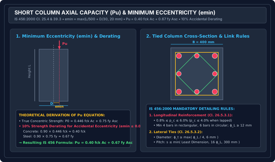
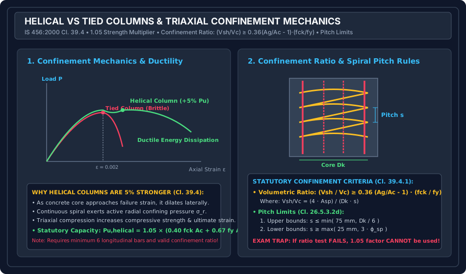
Diagram 2: Helical vs Tied Columns & Confinement Geometry
The diagram below illustrates the ductile stress-strain response of helically confined columns, the factor, spiral geometry (), and statutory pitch limits ().
       HELICAL REINFORCEMENT & CONFINEMENT RATIO
 ┌─────────────────────────────────────────────────────────────┐
 │  Pu,helical = 1.05 × (0.40 fck Ac + 0.67 fy Asc)            │
 │                                                             │
 │  Core Diameter Dk = D - 2·c_nom                             │
 │  Pitch s: 25 mm ≤ s ≤ min(75 mm, Dk/6)                      │
 │                                                             │
 │  Confinement Check:                                         │
 │  (4·Asp) / (Dk · s) ≥ 0.36 · (Ag/Ac - 1) · (fck / fy)       │
 └─────────────────────────────────────────────────────────────┘
7. Step-by-Step Design Procedures
                       SHORT COLUMN DESIGN WORKFLOW
                                     │
 ┌───────────────────────────────────┴───────────────────────────────────┐
 │ 1. Classify Column: Verify lex/D < 12 and ley/b < 12.                 │
 │ 2. Compute Minimum Eccentricities:                                    │
 │    - ex,min = max(L/500 + D/30, 20 mm)                                │
 │    - ey,min = max(L/500 + b/30, 20 mm)                                │
 │ 3. Check Cl. 39.3 Applicability: ex,min ≤ 0.05 D and ey,min ≤ 0.05 b. │
 │ 4. Estimate Gross Area Ag:                                            │
 │    Assuming target steel ratio p (e.g. 1.0% to 2.0%):                 │
 │    Pu = [0.40 fck (1 - p) + 0.67 fy p] · Ag                           │
 │ 5. Select Dimensions B × D (or Diameter D): Ag = B · D.               │
 │ 6. Calculate Required Steel Asc:                                      │
 │    Asc = (Pu - 0.40 fck Ag) / (0.67 fy - 0.40 fck)                    │
 │ 7. Check Steel Limits: 0.8% Ag ≤ Asc ≤ 4.0% Ag.                       │
 │ 8. Design Lateral Ties / Helical Spirals:                             │
 │    - Tied: ϕt ≥ max(ϕL/4, 6 mm); s ≤ min(b, 16ϕL, 300 mm)             │
 │    - Helical: Verify (Vsh/Vc) ≥ 0.36(Ag/Ac-1)(fck/fy); 25 ≤ s ≤ 75 mm │
 └───────────────────────────────────────────────────────────────────────┘
8. Pre-Calculated Solved Numerical Examples
Example 1: Design of a Short Axially Loaded Tied Column (IS 456 Clause 39.3)
Problem Statement:
Design a short square reinforced concrete column to support a factored axial compressive load of . The unsupported length of the column is and both ends are partially restrained against rotation (). Target longitudinal steel percentage is .
Materials: Concrete M25 (), Steel Fe 415 ().
Solution:
Step 1: Determine Required Gross Area (): Using target steel :
For a square column:
Provided gross area .
Step 2: Check Slenderness Ratio (Clause 25.1.2):
Step 3: Check Minimum Eccentricity (Clause 25.4):
Statutory minimum .
Check limit:
Since , Clause 39.3 formula is strictly applicable.
Step 4: Compute Required Longitudinal Steel ():
Minimum steel check (Clause 26.5.3.1):
Since , provide statutory minimum steel .
Provide :
This satisfies .
Step 5: Design Lateral Ties (Clause 26.5.3.2):
- Tie diameter:
- Pitch of ties:
Provide ties @ c/c (outer closed hoop plus internal diamond tie).
Example 2: Helically Reinforced Circular Column Design & Confinement Verification
Problem Statement:
A circular reinforced concrete column of diameter and unsupported length is reinforced with longitudinal bars. The materials are concrete M30 () and steel Fe 415 (). Clear cover to helical reinforcement is .
Determine:
- The ultimate axial load capacity with helical reinforcement ().
- The maximum permissible pitch for an helical spiral to satisfy the IS 456:2000 Clause 39.4.1 confinement condition.
Solution:
Step 1: Gross and Core Dimensions:
- Gross diameter :
- Core diameter :
- Ratio
Step 2: Longitudinal Steel & Core Concrete Area:
Step 3: Axial Capacity with Helical 1.05 Factor (Clause 39.4):
With helical reinforcement:
Step 4: Check Confinement Ratio & Determine Spiral Pitch (): Using spiral bar (): Per Clause 39.4.1:
Evaluating the right-hand side:
Now equating:
Step 5: Check Codal Pitch Bounds (Clause 26.5.3.2d):
- Upper bound 1: .
- Upper bound 2: .
- Confinement requirement: .
- Lower bound 1: .
- Lower bound 2: .
Therefore, the pitch must satisfy .
Adopt an spiral at a pitch of c/c.
This safely satisfies all confinement and detailing rules.
Example 3: Slenderness Classification & Minimum Eccentricity Check
Problem Statement:
A reinforced concrete column of cross-section and has a clear unsupported length . In the major axis direction (plane of ), the column is pinned at both ends (). In the minor axis direction (plane of ), the column is fixed at both ends ().
Determine:
- Whether the column is short or slender about each axis.
- The minimum eccentricity about both axes and verify whether the simplified axial formula of Clause 39.3 can be used.
Solution:
Step 1: Slenderness Ratio Check (Clause 25.1.2):
- Major axis:
- Minor axis:
Since both and , the column is classified as a Short Column.
Step 2: Minimum Eccentricity Calculation (Clause 25.4):
- About major axis (plane of ):
- About minor axis (plane of ):
Step 3: Check and Limits:
- In X direction:
- In Y direction:
Engineering Conclusion:
Because , Clause 39.3 formula CANNOT be used. The column must be designed for combined axial load and uniaxial bending moment () about the minor axis!
9. Engineering Misconceptions & Site Detailing Pitfalls
┌────────────────────────────────────────┬────────────────────────────────────────┬────────────────────────────────────────┐
│ Site Error / Detailing Defect          │ Engineering Consequence                │ IS 456:2000 Mandatory Remedy         │
├────────────────────────────────────────┼────────────────────────────────────────┼────────────────────────────────────────┤
│ Designing a column for pure concentric │ Accidental moments cause premature     │ Always enforce statutory emin =        │
│ load without minimum eccentricity emin │ compression edge crushing and failure! │ max(L/500 + D/30, 20 mm).              │
├────────────────────────────────────────┼────────────────────────────────────────┼────────────────────────────────────────┤
│ Using Cl. 39.3 formula when emin       │ Column is under-designed; failure to   │ When emin > 0.05 D, design as a member │
│ exceeds 0.05 D                         │ account for significant bending moment!│ under combined axial load and bending. │
├────────────────────────────────────────┼────────────────────────────────────────┼────────────────────────────────────────┤
│ Applying the 1.05 helical multiplier   │ Inadequate confinement; spiral fails to│ 1.05 factor is permitted ONLY when     │
│ when pitch s violates confinement ratio│ prevent core crushing; sudden failure! │ (Vsh/Vc) ≥ 0.36(Ag/Ac - 1)(fck/fy).    │
├────────────────────────────────────────┼────────────────────────────────────────┼────────────────────────────────────────┤
│ Providing 4 longitudinal bars in a     │ Spiral cannot be held securely in a    │ Circular / helical columns MUST have a │
│ circular helical column                │ true circle; bars buckle prematurely.  │ MINIMUM OF 6 BARS (Cl. 26.5.3.1).      │
├────────────────────────────────────────┼────────────────────────────────────────┼────────────────────────────────────────┤
│ Exceeding tie pitch of 16 ϕL           │ Compression bars buckle outward under  │ Lateral tie pitch must be ≤            │
│ (e.g. using 350 mm spacing)            │ service loads, splitting cover off.    │ min(b_min, 16 ϕL, 300 mm).             │
└────────────────────────────────────────┴────────────────────────────────────────┴────────────────────────────────────────┘
10. Comparative Analysis: Tied Columns vs Helical Columns
| Detailing Feature | Tied Column (IS 456 Cl. 39.3) | Helically Reinforced Column (IS 456 Cl. 39.4) |
|---|---|---|
| Transverse Steel | Discrete individual closed ties / hoops | Continuous spiral helix |
| Minimum Longitudinal Bars | 4 bars (rectangular), 6 (circular) | 6 bars mandatory |
| Design Axial Capacity | ||
| Confinement Action | Very weak; ties only prevent bar buckling | Active triaxial confining pressure on core |
| Failure Mode | Brittle; sudden cover spalling and buckling | Ductile; core sustains load to high strains |
| Pitch Limits | ||
| Confinement Verification | Not required | Mandatory: |
11. Competitive Exam Traps & High-Yield Takeaways
[!CAUTION] GATE / ESE High-Yield Trap Checklist:
- Short Column Boundary: Both and . If either is , it is slender!
- Pedestal Boundary: .
- Minimum Eccentricity Formula: . Uses unsupported length , not effective length !
- Applicability Threshold for Formula: . For , (statutory always violates for !).
- Helical Confinement Factor: Exactly ( enhancement).
- Confinement Formula Multiplier: . Remember the constant!
- Spiral Pitch Bounds: and .
- Minimum Bars: 4 for rectangular, 6 for circular. Minimum bar size is . Minimum steel is .
12. Practice Questions & Exercises
Question 1 (GATE CE)
A reinforced concrete column of size has an unsupported length of . The minimum eccentricity for which the column must be designed per IS 456:2000 is:
- (A)
- (B)
- (C)
- (D)
Answer: (B)
Explanation:
.
However, IS 456 Clause 25.4 mandates that shall not be less than . Hence, .
Question 2 (UPSC ESE)
In a helically reinforced circular column of diameter with core diameter , the ratio of the volume of helical reinforcement to the volume of the core concrete per unit pitch shall not be less than:
- (A)
- (B)
- (C)
- (D)
Answer: (A)
Explanation:
Per IS 456:2000 Clause 39.4.1, the volumetric confinement ratio must satisfy .
Question 3 (SSC JE)
As per IS 456:2000, what is the maximum pitch of lateral ties in an axially loaded short column of cross-section reinforced with bars of and bars of ?
- (A)
- (B)
- (C)
- (D)
Answer: (A)
Explanation:
Pitch .