Singly Reinforced Rectangular Beams in Flexure (IS 456:2000)
In this chapter (3 topics)
On this page
- 1. Introduction & Conceptual Foundations
- Key Geometric Definitions:
- 2. Equilibrium Equations & Actual Neutral Axis Depth (xu)
- Representation in Terms of Steel Percentage (pt)
- 3. Classification of Cross-Sections
- 3.1 Under-Reinforced Section (xu < xu,max or Ast < Ast,lim)
- 3.2 Balanced (Limiting) Section (xu = xu,max or Ast = Ast,lim)
- 3.3 Over-Reinforced Section (xu > xu,max or Ast > Ast,lim)
- 4. Formulations for Ultimate Moment of Resistance (Mu)
- 4.1 Under-Reinforced Sections (xu ≤ xu,max)
- 4.2 Balanced Sections (xu = xu,max)
- 4.3 Over-Reinforced Sections (xu > xu,max)
- 5. Closed-Form Quadratic Solution for Required Tension Steel (Ast)
- Code Rebar Bounds (IS 456:2000 Clause 26.5.1.1)
- 6. Systematic Analysis Procedure for Singly Reinforced Beams
- 7. Systematic Design Procedure for Singly Reinforced Beams
- 8. Worked Numerical Examples
- Problem 1: Flexural Capacity Analysis of an Under-Reinforced Beam
- Problem 2: Analysis of an Over-Reinforced Beam with Code Capping Check
- Problem 3: Complete Design of a Singly Reinforced Rectangular Beam
- 9. Common Misconceptions & Exam Pitfalls
- 10. Comparative Summary & Master Formula Sheet
- Master Equations for Singly Reinforced Beams
- 11. Practice Questions & Competitive Examination Problems
- Question 1 (GATE CE — 1 Mark)
- Question 2 (UPSC ESE — Objective)
- Question 3 (SSC JE — Technical)
- Question 4 (State AE — Analytical)
- Question 5 (GATE CE — 2 Marks)
- Question 6 (UPSC ESE — Conventional)
- 12. References & Code Standards
1. Introduction & Conceptual Foundations
A singly reinforced beam is a structural flexural member in which longitudinal steel reinforcement is provided exclusively in the tension zone (the bottom face in simply supported beams and the top face in cantilevers) to resist all tensile forces developed under transverse bending. Concrete in the compression zone resists all compressive forces, while the tensile capacity of concrete is neglected once flexural micro-cracks form.
In limit state flexural mechanics, the bending capacity of a singly reinforced beam is generated by an internal resisting couple formed between:
- The resultant compressive force () acting through the centroid of the concrete compressive stress block.
- The resultant tensile force () acting through the centroid of the longitudinal tension reinforcement ().
+----------------------------------------------------------------------------------------------------+
|                                 SINGLY REINFORCED BEAM CROSS-SECTION                               |
+----------------------------------------------------------------------------------------------------+
|                                                                                                    |
|          <-------- b -------->                                                                     |
|       +-------------------------+  ---                                                             |
|       |                         |   |                                                              |
|       |    COMPRESSION ZONE     |   |                                                              |
|       |    (Concrete Resists)   |   | xu (Depth of Neutral Axis)                                   |
|   ----+-------------------------+---+--- NA                                                        |
|   :   |  . . . . . . . . . . .  |   |                                                              |
|   :   |   CRACKED TENSION ZONE  |   |                                                              |
|   D   |   (Concrete Neglected)  |   | d (Effective Depth)                                          |
|   :   |                         |   |                                                              |
|   :   |       (O) (O) (O)       |   |                                                              |
|   :   |    Ast (Tension Rebar)  |   |                                                              |
|   ----+-------------------------+---+---                                                           |
|       |                         | d' (Effective Cover = D - d)                                     |
|       +-------------------------+                                                                  |
+----------------------------------------------------------------------------------------------------+
Key Geometric Definitions:
- : Width of the rectangular beam section ().
- : Overall total depth of the beam section ().
- : Effective depth of the beam section (), defined as the distance from the extreme compression fiber to the centroid of the longitudinal tension reinforcement.
- : Effective cover to the center of tension reinforcement ().
- : Actual depth of the neutral axis from the extreme compression fiber at the ultimate limit state ().
- : Total cross-sectional area of longitudinal tension steel bars ().
2. Equilibrium Equations & Actual Neutral Axis Depth ()
At the ultimate limit state of collapse, the beam cross-section must satisfy internal translational equilibrium along its longitudinal axis ():
From the IS 456:2000 parabolic-rectangular stress block derived in RCC-01-03:
- Resultant compressive force in concrete:
- Resultant tensile force in steel (assuming the steel yields, i.e., under-reinforced or balanced):
Equating :
Solving for the Actual Depth of Neutral Axis ():
Representation in Terms of Steel Percentage ()
Let the percentage of tensile reinforcement be defined as:
Substituting into the expression for :
Physical Significance:
The actual depth of the neutral axis () is directly proportional to the amount of tension reinforcement () and the yield strength of the steel (), and inversely proportional to the beam width () and concrete compressive strength (). As more steel is added to a section, the neutral axis shifts downwards to mobilize a larger volume of concrete in compression to maintain horizontal equilibrium.
3. Classification of Cross-Sections
In the Limit State Method, cross-sections are classified into three distinct physical regimes by comparing the actual neutral axis depth () with the limiting neutral axis depth ():
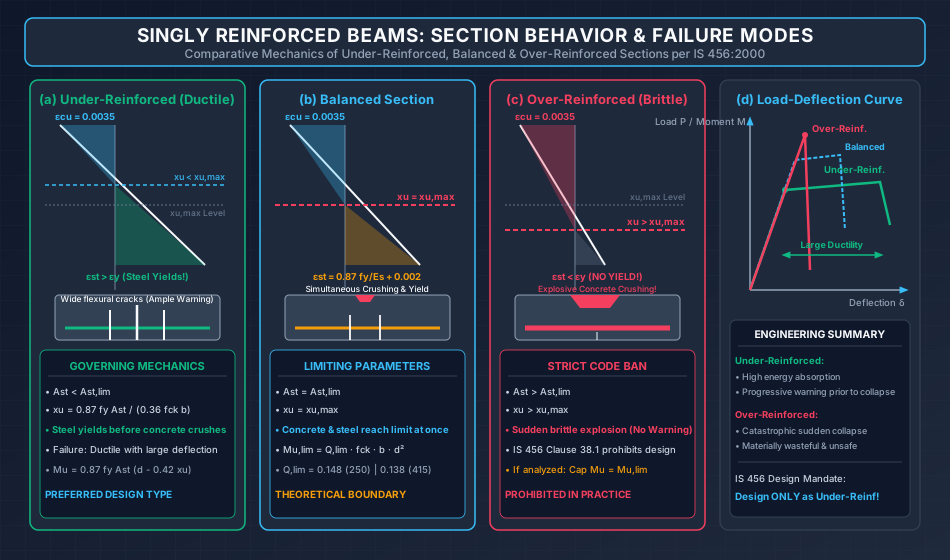
3.1 Under-Reinforced Section ( or )
- Mechanical Mechanism: The tension steel reaches its design yield strain () while the extreme concrete fiber compressive strain is still below its crushing capacity ().
- Behavior Under Overload: Once the steel yields, it enters a plastic elongation phase. As the bars stretch significantly, the neutral axis migrates upwards, widening flexural tensile cracks and inducing substantial vertical beam deflections.
- Failure Mode (Ductile / Warning-Rich): The large deflections and prominent tensile cracking provide clear visible warning long before the secondary crushing of concrete terminates the member's life.
- Design Philosophy: All structural flexural members MUST be designed as under-reinforced.
3.2 Balanced (Limiting) Section ( or )
- Mechanical Mechanism: The extreme concrete compressive fiber reaches its crushing strain () at the exact same instant that the tension reinforcement reaches its design yield strain ().
- Limiting Reinforcement Area ():
- Limiting Percentage ():
- Failure Mode: Simultaneous yielding of steel and crushing of concrete. Represents the theoretical upper bound of flexural capacity for a singly reinforced beam.
3.3 Over-Reinforced Section ( or )
- Mechanical Mechanism: The section contains an excess of tension reinforcement. The concrete reaches its ultimate crushing strain () while the steel strain remains below yield (, ).
- Failure Mode (Brittle / Catastrophic): Concrete crushes suddenly, explosively, and without prior warning. Tensile cracks remain narrow and deflections are minimal right up to the moment of catastrophic collapse.
- IS 456:2000 Strict Prohibition (Clause 38.1):
CODE MANDATE: Design of over-reinforced singly reinforced beams is STRICTLY PROHIBITED.
If an existing beam is analyzed and found to be over-reinforced (), its design moment of resistance must be capped at:Any additional steel provided beyond is considered structurally ineffective because the concrete crushes before the excess steel can be stressed to its yield strength.
4. Formulations for Ultimate Moment of Resistance ()
The moment of resistance is the capacity of the internal resisting couple ( or ), where the lever arm is .
4.1 Under-Reinforced Sections ()
Evaluating from the tension reinforcement side:
Substituting :
Approximating , this yields the authoritative IS 456:2000 Annex G Equation G-1.1:
Alternatively, evaluating from the concrete compression side:
(Both formulations yield identical numerical results when ).
4.2 Balanced Sections ()
When , the moment capacity reaches the Limiting Moment of Resistance ():
| Steel Grade | Limiting Factor | Limiting Moment Formulation | |
|---|---|---|---|
| Fe 250 | |||
| Fe 415 | |||
| Fe 500 |
4.3 Over-Reinforced Sections ()
Per IS 456:2000, the moment of resistance of an over-reinforced singly reinforced beam is restricted to:
5. Closed-Form Quadratic Solution for Required Tension Steel ()
In design problems, the factored bending moment , beam dimensions (), concrete grade (), and steel grade () are known. The task is to calculate the required steel area .
Starting from IS 456 Annex G Eq. G-1.1:
Dividing across by :
Let the reinforcement ratio be . Rearranging into standard quadratic form :
Solving for using the quadratic formula and taking the physically meaningful smaller root (under-reinforced solution):
Since :
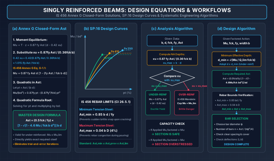
Code Rebar Bounds (IS 456:2000 Clause 26.5.1.1)
-
Minimum Tension Reinforcement ():
Engineering Purpose: Prevents sudden, explosive brittle fracture when concrete reaches its modulus of rupture (). The steel must be capable of carrying the full cracking moment () upon concrete crack initiation.
-
Maximum Tension Reinforcement ():
Engineering Purpose: Prevents severe rebar congestion, ensuring concrete aggregates can freely flow around bars and undergo proper vibratory compaction.
6. Systematic Analysis Procedure for Singly Reinforced Beams
+----------------------------------------------------------------------------------------------------+
|                                    ANALYSIS ALGORITHM (CHECKING CAPACITY)                          |
+----------------------------------------------------------------------------------------------------+
|                                                                                                    |
|   Step 1: Extract Given Data: b, d, D, fck, fy, and provided rebar Ast = n * (pi * phi^2 / 4)      |
|                                                                                                    |
|   Step 2: Calculate Actual Neutral Axis Depth (xu):                                                |
|           xu = (0.87 * fy * Ast) / (0.36 * fck * b)                                               |
|                                                                                                    |
|   Step 3: Calculate Limiting Neutral Axis Depth (xu,max):                                          |
|           xu,max = k * d  (where k = 0.53 for Fe 250, 0.48 for Fe 415, 0.46 for Fe 500)           |
|                                                                                                    |
|   Step 4: Classify the Cross-Section:                                                              |
|           [CASE A] xu < xu,max  --> UNDER-REINFORCED (Ductile yield governs)                       |
|                    Mu = 0.87 * fy * Ast * d * [1 - (fy * Ast) / (fck * b * d)]                     |
|           [CASE B] xu = xu,max  --> BALANCED SECTION (Limiting capacity)                           |
|                    Mu = Mu,lim = Q,lim * fck * b * d^2                                             |
|           [CASE C] xu > xu,max  --> OVER-REINFORCED (Concrete crushing governs)                    |
|                    Cap capacity per IS 456: Mu = Mu,lim = Q,lim * fck * b * d^2                    |
|                                                                                                    |
|   Step 5: Compare Resisting Capacity with Applied Factored Load:                                   |
|           If Mu >= Mu,applied --> SAFE;  If Mu < Mu,applied --> REDESIGN REQUIRED                  |
+----------------------------------------------------------------------------------------------------+
7. Systematic Design Procedure for Singly Reinforced Beams
+----------------------------------------------------------------------------------------------------+
|                                    DESIGN ALGORITHM (SIZING & DETAILING)                           |
+----------------------------------------------------------------------------------------------------+
|                                                                                                    |
|   Step 1: Establish Factored Design Moment (Mu):                                                   |
|           Mu = 1.5 * M_service (considering DL, LL, etc.)                                          |
|                                                                                                    |
|   Step 2: Select Concrete Grade (fck), Steel Grade (fy), and Choose Beam Width (b):                |
|           Architectural width typically b = 230 mm, 250 mm, or 300 mm                              |
|                                                                                                    |
|   Step 3: Determine Minimum Effective Depth (d_min) for Balanced Condition:                        |
|           Mu = Q,lim * fck * b * d_min^2  -->  d_min = sqrt(Mu / (Q,lim * fck * b))                |
|                                                                                                    |
|   Step 4: Adopt Depth to Guarantee Under-Reinforced Behavior:                                      |
|           Select effective depth d >= d_min (e.g., round up to nearest 10 or 25 mm).               |
|           Calculate overall depth D = d + effective cover (nominal cover + stirrup dia + phi/2).   |
|                                                                                                    |
|   Step 5: Calculate Required Tension Steel Area (Ast):                                             |
|           Ast = (0.5 * fck / fy) * [1 - sqrt(1 - 4.6 * Mu / (fck * b * d^2))] * b * d             |
|                                                                                                    |
|   Step 6: Verify Code Reinforcement Limits:                                                        |
|           Ast,min = (0.85 * b * d) / fy  <-- Ensure Ast >= Ast,min                                 |
|           Ast,max = 0.04 * b * D         <-- Ensure Ast <= Ast,max                                 |
|                                                                                                    |
|   Step 7: Rebar Selection & Spacing Detailing:                                                     |
|           Choose bar diameter phi, compute number of bars n = Ast / (pi * phi^2 / 4).              |
|           Check clear horizontal spacing >= phi_bar or 25 mm (IS 456 Clause 26.3.2).              |
+----------------------------------------------------------------------------------------------------+
8. Worked Numerical Examples
Problem 1: Flexural Capacity Analysis of an Under-Reinforced Beam
Problem Statement:
A simply supported reinforced concrete beam has width , effective depth , and overall depth . The beam is reinforced with bars of diameter in the tension zone. Concrete grade is M20 () and steel grade is Fe 415 ().
- Determine the actual depth of the neutral axis ().
- Classify the section.
- Calculate the ultimate factored moment of resistance () using both the tension and Annex G formulations.
Step-by-Step Solution:
Part 1: Area of Tension Steel ()
Part 2: Actual Depth of Neutral Axis ()
Part 3: Limiting Depth of Neutral Axis & Classification For Fe 415 steel:
Since , the section is UNDER-REINFORCED. Tension steel yields before concrete crushes, ensuring ductile failure.
Part 4: Moment of Resistance ()
-
Method 1: Tension Formulation ():
-
Method 2: IS 456 Annex G Eq. G-1.1:
(The difference is due to the analytical lever arm coefficient vs codified ).
Problem 2: Analysis of an Over-Reinforced Beam with Code Capping Check
Problem Statement:
Evaluate the flexural moment of resistance for the cross-section from Problem 1 (, M20, Fe 415) if the tension steel is heavily increased to bars of diameter ().
Step-by-Step Solution:
Part 1: Actual Neutral Axis Depth ()
Part 2: Classification For Fe 415 steel:
Since (and in fact ), the section is HEAVILY OVER-REINFORCED.
Part 3: Application of IS 456 Code Limit Per IS 456:2000 Clause 38.1:
The section will suffer sudden, brittle crushing of concrete before steel yields. The moment of resistance cannot be evaluated from the under-reinforced formula. It must be capped at the limiting moment of resistance ():
For Fe 415, :
Important Examination Finding:
Even though the rebar area was increased by (), the usable moment capacity increased by only () due to concrete crushing limits. The extra of steel is completely wasted, illustrating why over-reinforced sections are both uneconomical and dangerous.
Problem 3: Complete Design of a Singly Reinforced Rectangular Beam
Problem Statement:
Design a simply supported singly reinforced rectangular beam to support a factored bending moment . The beam width is restricted to due to architectural masonry wall thickness. Use M25 grade concrete () and Fe 500 grade steel (). Assume an effective cover of .
Step-by-Step Solution:
Part 1: Minimum Effective Depth ()
For Fe 500 steel, the limiting moment factor is :
Part 2: Cross-Section Sizing To ensure under-reinforced behavior ():
- Adopt .
- Overall depth .
- Section dimensions: .
Part 3: Required Area of Tension Reinforcement ()
Using the closed-form quadratic formula:
Compute the term under the radical:
Part 4: Code Reinforcement Bounds Check
- Minimum tension steel (IS 456 Clause 26.5.1.1):
- Maximum tension steel:
- Limiting steel for balanced section: Since , the section is strictly under-reinforced.
Part 5: Rebar Detailing & Capacity Verification
- Provide 2 bars of 20 mm dia () plus 1 bar of 16 mm dia (): Notice: .
- Neutral axis with provided steel:
- Factored moment capacity with provided steel: Design is fully safe and code-compliant.
9. Common Misconceptions & Exam Pitfalls
[!WARNING] Pitfall 1: Attempting to Use for Over-Reinforced Sections
In an over-reinforced section (), steel never yields (). Substituting is fundamentally invalid and grossly overestimates capacity. The correct exam procedure is to immediately cap the moment at .
[!WARNING] Pitfall 2: Neglecting the Minimum Steel Criterion ()
If an excessively deep beam is provided for deflection control, the calculated from bending moments can drop below . Failing to provide risks sudden catastrophic snapping of rebar upon initial concrete cracking.
[!CAUTION] Pitfall 3: Using Gross Depth Instead of Effective Depth in Formulas
and depend strictly on effective depth . Using produces large, un-conservative errors in exam calculations.
[!IMPORTANT] Pitfall 4: Miscalculating the Quadratic Radical
When calculating from , the term inside the square root is . Ensure is converted to (multiply by ) before division.
10. Comparative Summary & Master Formula Sheet
Master Equations for Singly Reinforced Beams
| Parameter | Governing Mathematical Formula | Remarks / Code Reference |
|---|---|---|
| Actual NA Depth () | Internal Equilibrium | |
| Limiting NA Depth () | (Fe 250), (Fe 415), (Fe 500) | |
| Under-Reinforced Moment () | IS 456 Annex G Eq. G-1.1 | |
| Limiting Moment () | (250), (415), (500) | |
| Minimum Effective Depth () | Balanced singly reinforced boundary | |
| Required Steel Area () | Exact closed-form quadratic root | |
| Minimum Steel Area () | IS 456 Clause 26.5.1.1(a) | |
| Maximum Steel Area () | IS 456 Clause 26.5.1.1(b) |
11. Practice Questions & Competitive Examination Problems
Question 1 (GATE CE — 1 Mark)
A reinforced concrete beam is designed as an under-reinforced section. Which of the following statements is TRUE regarding its failure mechanism?
- (A) Concrete crushes before steel reaches its yield point
- (B) Steel yields first, accompanied by large deflections and wide cracks before collapse
- (C) Steel and concrete reach their ultimate capacities simultaneously
- (D) Failure is sudden and brittle without any warning
Answer: (B)
Explanation: In under-reinforced sections (), steel yields at prior to concrete crushing, providing ductile warning.
Question 2 (UPSC ESE — Objective)
If a singly reinforced rectangular beam is analyzed and found to have , the design moment of resistance as per IS 456:2000 is taken as:
- (A)
- (B)
- (C)
- (D) Zero
Answer: (C)
Explanation: IS 456 prohibits over-reinforced design and mandates capping the capacity at .
Question 3 (SSC JE — Technical)
The minimum area of tension reinforcement in a rectangular beam of width and effective depth using Fe 415 grade steel as per IS 456:2000 is:
- (A)
- (B)
- (C)
- (D)
Answer: (A)
Explanation: .
Question 4 (State AE — Analytical)
A rectangular beam of size (effective depth) is cast with M25 concrete and Fe 500 steel. The minimum effective depth required to resist a factored moment of as a balanced section is:
- (A)
- (B)
- (C)
- (D)
Answer: (A)
Explanation: For Fe 500, . .
Question 5 (GATE CE — 2 Marks)
A singly reinforced rectangular beam with and is made of M20 concrete and Fe 415 steel. If the tension steel area provided is , the depth of the neutral axis in is:
- (A)
- (B)
- (C)
- (D)
Answer: (A)
Explanation: .
Question 6 (UPSC ESE — Conventional)
Derive the closed-form quadratic expression for the required tension reinforcement area in terms of factored moment , cross-sectional dimensions and , and material grades and .
Answer Summary: Starting from , define reinforcement ratio , formulate the quadratic equation , and solve for the lower root to obtain .
12. References & Code Standards
- IS 456:2000 (Reaffirmed 2021): Plain and Reinforced Concrete — Code of Practice, Section 5 (Clause 26: Requirements of Reinforcement, Clause 38: Limit State of Collapse — Flexure, Annex G: Moments of Resistance and Section Properties).
- SP:16 (1980): Design Aids for Reinforced Concrete to IS: 456-1978, Bureau of Indian Standards, New Delhi.
- Pillai, S. U., & Menon, D. (2021): Reinforced Concrete Design, 4th Edition, McGraw-Hill Education, India.
- Varghese, P. C. (2009): Limit State Design of Reinforced Concrete, 2nd Edition, PHI Learning Pvt. Ltd., New Delhi.
- Jain, A. K. (2012): Reinforced Concrete: Limit State Design, 7th Edition, Nem Chand & Bros, Roorkee.