Analysis & Design of Prestressed Concrete Beams
In this chapter (4 topics)
On this page
- 1. Introduction & Overview of Prestressed Flexural Mechanics
- 2. The Three Fundamental Concepts of Analysis
- 2.1 Concept 1: Stress Concept (Combined Direct Stress & Flexure)
- 2.2 Concept 2: Internal Couple / C-Line Concept (Strength Approach)
- 2.3 Concept 3: Load Balancing Concept (T.Y. Lin's Approach)
- 3. Kern Points & Permissible Cable Profile Zone (Envelope)
- 3.1 Kern Points (Middle-Third Rule)
- 3.2 Limiting Cable Eccentricities (The Cable Zone)
- 4. Continuous Prestressed Beams & Concordant Profiles
- 4.1 Primary vs Secondary Moments
- 4.2 Concordant Cable Profile
- 4.3 Guyon's Theorem of Linear Transformation
- 5. Ultimate Flexural Strength per IS 1343:2012 (Limit State of Collapse)
- 5.1 Failure Modes
- 5.2 Bonded Beams Ultimate Flexural Capacity (IS 1343:2012 Cl. 23.4 / Table 11)
- 6. Worked Numerical Examples with Complete Step-by-Step Verification
- Problem 1: Beam Analysis by All Three Concepts (Stress, Internal Couple, Load Balancing)
- Problem 2: Kern Points & Limiting Cable Profile Envelope
- Problem 3: Ultimate Flexural Strength of Bonded T-Beam (IS 1343:2012 Table 11)
- 7. Comparative Technical Matrix: The Three Analysis Approaches
- 8. Construction Practices & Site Pitfalls
- 9. Competitive Examination Traps & Problem-Solving Shortcuts
- 10. Practice Problems & Examination Review Exercises
- Level 1: Objective Conceptual (SSC JE / RRB JE)
- Level 2: Multi-Concept Analytical (GATE CE)
- Level 3: Conventional Design Problem (UPSC ESE Mains)
- 11. Complete Topic Architecture & Upstream/Downstream Dependencies
- 12. Verification & Standards References
1. Introduction & Overview of Prestressed Flexural Mechanics
The structural analysis of a prestressed concrete beam involves determining the state of stress across the section under varying combinations of prestressing force and external gravity loads throughout two distinct lifecycle regimes:
- Transfer Stage (Initial State): Tendons tensioned and anchored into green concrete; external load consists solely of the beam's own self-weight (). The prestress force is at its maximum initial value (), creating a critical risk of top fiber tensile cracking (due to hogging) and bottom fiber compressive crushing.
- Service Stage (Working State): Long-term prestress losses have fully transpired (, with ); full sustained superimposed dead load and transient live loads act on the member (). The critical risk inverts to bottom fiber tensile cracking (sagging) and top fiber compressive crushing.
                        STAGES OF PRESTRESSED BEAM BEHAVIOR
                                         │
         ┌───────────────────────────────┴───────────────────────────────┐
         ▼                                                               ▼
   TRANSFER STAGE (Initial)                                    SERVICE STAGE (Final)
   • Prestress Force: Maximum (Pi)                             • Prestress Force: Effective (Pe = η·Pi)
   • External Moment: Minimum (Msw only)                       • External Moment: Maximum (Msw + Mlive)
   • Critical Top Fiber: Risk of TENSION                       • Critical Top Fiber: Risk of COMPRESSION
   • Critical Bottom Fiber: Risk of COMPRESSION                • Critical Bottom Fiber: Risk of TENSION
To analyze these stress states, classical structural engineering provides three distinct, mathematically equivalent conceptual frameworks: the Stress Concept, the Internal Couple Concept, and the Load Balancing Concept.
2. The Three Fundamental Concepts of Analysis
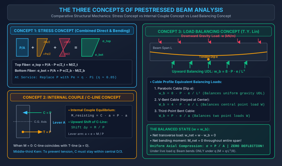
2.1 Concept 1: Stress Concept (Combined Direct Stress & Flexure)
The member is treated as an elastic, homogeneous structural element subjected to an external axial compressive force acting at an eccentricity , producing an internal hogging bending moment that counteracts the external sagging gravity moment .
By linear superposition of the three stress components:
- Direct Compressive Stress: (uniform compression across entire cross-section).
- Prestress Eccentricity Stress: (tension at top, compression at bottom for positive downward eccentricity).
- External Gravity Moment Stress: (compression at top, tension at bottom).
Net Extreme Fiber Stresses:
- Top Fiber Stress:
- Bottom Fiber Stress:
(Sign Convention: Compression, Tension. and are the section moduli for top and bottom fibers).
At the service stage, replace with effective prestress and with total service moment .
2.2 Concept 2: Internal Couple / C-Line Concept (Strength Approach)
Analogous to conventional reinforced concrete, prestressed concrete is conceptualized as an internal resisting couple formed by two equal and opposite forces:
- Tensile Force (): Provided by the tensioned high-tensile steel tendon ().
- Compressive Force (): Provided by the compressive resultant in the concrete ().
For static equilibrium under pure prestress with zero external moment (), the line of action of (the -line or thrust line) must align collinearly with the tendon (-line), located at eccentricity below the centroid ().
When an external sagging bending moment is applied, the tension in a post-tensioned tendon remains practically constant (until cracking). To equilibrate , the compressive resultant must shift vertically upward by an eccentric distance :
The internal lever arm between and becomes:
The internal resisting moment is:
The position of the -line with respect to the section centroid is:
The extreme fiber stresses can be computed directly from acting at eccentricity :
2.3 Concept 3: Load Balancing Concept (T.Y. Lin's Approach)
Introduced by Professor T.Y. Lin in 1963, the load balancing concept visualizes the prestressing tendon as an internal suspension cable. As the tendon is tensioned under force , its curvature exerts lateral transverse forces on the surrounding concrete that directly counteract and balance the external gravity loads.
1. Parabolic Cable Trajectory (Balancing Uniform Gravity UDL)
Consider a parabolic cable with central sag across span :
The lateral radial pressure exerted by a tensioned cable of curvature is . Since , the tendon exerts a strictly uniform upward equivalent distributed load () along the entire span:
2. Bent (Harped) Tendon Profile (Balancing Concentrated Point Load)
A tendon harped at midspan with a sharp V-bend of eccentricity : The upward vertical component exerted at the midspan kink is:
3. The Balanced State ()
If the prestressing parameters are selected such that the upward balancing load equals the downward external dead load ():
- Net Transverse Load: .
- Net Bending Moment: at every section along the entire span!
- Net Deflection: (the beam remains perfectly flat!).
- Stress State: The beam behaves as an axially loaded column subjected to pure, uniform axial compression:
Under any superimposed live load , the beam bends only under the un-balanced load , behaving as a simple beam with bending moment .
3. Kern Points & Permissible Cable Profile Zone (Envelope)
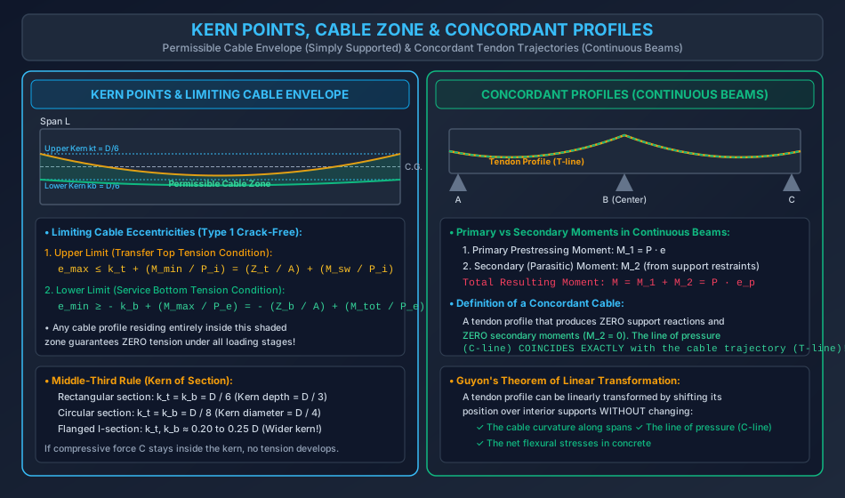
3.1 Kern Points (Middle-Third Rule)
The kern (core) of a cross-section represents the geometric zone within which the resultant compressive thrust must act so that no tensile stress develops anywhere in the section.
By setting in the flexure formula:
- Upper Kern Limit (): Distance above the centroid such that bottom fiber stress :
- Lower Kern Limit (): Distance below the centroid such that top fiber stress :
Kern Distances for Standard Shapes:
- Rectangular Section (): . The kern occupies the central depth (the classical Middle-Third Rule).
- Circular Section (Diameter ): (central diameter).
- Symmetric I-Section: (significantly wider kern due to flange concentration).
3.2 Limiting Cable Eccentricities (The Cable Zone)
To ensure that a beam remains crack-free (Type 1 member: ) under both initial transfer and final service conditions, the tendon eccentricity must lie within an envelope defined by two boundary curves:
-
Upper Limiting Eccentricity (): Governed by the transfer stage to prevent tension in the top fiber under minimum external moment ():
-
Lower Limiting Eccentricity (): Governed by the service stage to prevent tension in the bottom fiber under maximum external moment ():
The shaded region between and along the span represents the permissible cable zone. Any cable profile lying entirely inside this zone guarantees that the beam remains 100% crack-free at all load stages.
4. Continuous Prestressed Beams & Concordant Profiles
In statically indeterminate (continuous) prestressed concrete beams, tensioning the tendons induces secondary redundant reactions at the interior supports:
4.1 Primary vs Secondary Moments
- Primary Moment (): The direct internal bending moment produced by tendon eccentricity:
- Secondary (Parasitic / Hyperstatic) Moment (): Tendon curvature causes the beam to camber upward. Because intermediate interior supports restrain this upward deflection, downward vertical reactions are induced, creating secondary moments: (Note: Secondary moments vary linearly between support points).
- Total Resulting Moment (): where is the eccentricity of the resultant pressure line (-line).
4.2 Concordant Cable Profile
Definition: A concordant cable is a tendon profile in a continuous beam that produces zero secondary reactions and zero secondary moments () at all supports.
For a concordant profile:
- The line of pressure (-line) coincides identically with the cable profile (-line): .
- Primary moments equal total moments ().
- A concordant profile can always be obtained by choosing a cable trajectory that follows the shape of the bending moment diagram produced by any system of external loads on the continuous beam!
4.3 Guyon's Theorem of Linear Transformation
Guyon's Theorem: In a continuous prestressed beam, a tendon profile can be linearly transformed by shifting its position over any interior support (by distance ) while keeping its ends fixed and preserving its span curvatures, without altering the position of the line of pressure (-line) and without changing the net flexural stresses in the concrete.
Design Significance: If a concordant cable requires an impracticably small concrete cover over an intermediate support, the engineer can linearly transform the tendon upward into the flange to provide adequate cover, knowing that the structural line of pressure (-line) and concrete stresses will remain 100% unaffected!
5. Ultimate Flexural Strength per IS 1343:2012 (Limit State of Collapse)
Under ultimate failure loads, prestressed concrete beams behave in flexure similarly to conventional reinforced concrete, with large tensile deformations, cracking, and plastification of the compressive concrete block.
5.1 Failure Modes
- Under-Reinforced Section: Tension steel reaches plastic elongation (), followed by large deflections, wide cracking, and ductile crushing of compressive concrete.
- Over-Reinforced Section: Concrete in the compression zone crushes abruptly before the high-tensile steel yields (brittle failure; strictly prohibited).
5.2 Bonded Beams Ultimate Flexural Capacity (IS 1343:2012 Cl. 23.4 / Table 11)
For rectangular sections or flanged sections where the neutral axis lies within the flange ():
- Compute the effective reinforcement ratio (reinforcement index):
- From IS 1343:2012 Table 11, determine:
- Stress in tendon at ultimate failure: (or ratio ).
- Neutral axis depth factor: .
| (Pre-tensioned & Bonded Post-tensioned) | ||
|---|---|---|
| 0.05 | 1.00 | 0.109 |
| 0.10 | 1.00 | 0.217 |
| 0.15 | 0.94 | 0.326 |
| 0.20 | 0.88 | 0.435 |
| 0.25 | 0.82 | 0.542 |
| 0.30 | 0.77 | 0.650 |
| 0.40 | 0.69 | 0.780 |
- Verify whether . If , the flanged beam is treated as a rectangular section of width .
- Ultimate Resisting Moment ():
6. Worked Numerical Examples with Complete Step-by-Step Verification
Problem 1: Beam Analysis by All Three Concepts (Stress, Internal Couple, Load Balancing)
Statement:
A prestressed concrete beam of rectangular cross-section spans . It is prestressed with an effective force using a parabolic cable having a central dip below the centroid at midspan and concentric () at the supports. The beam supports an imposed live load . Concrete density is .
Calculate the top and bottom fiber stresses at midspan using:
(a) The Stress Concept
(b) The Internal Couple / C-Line Concept
(c) The Load Balancing Concept
Verify that all three approaches yield identical numerical results.
Solution:
Step 1: Section Properties & Gravity Loads:
- Cross-sectional area: .
- Section modulus:
- Self-weight: .
- Total gravity load: .
- Total midspan bending moment:
(a) Analysis by Concept 1: Stress Concept:
- Direct compressive stress:
- Prestress eccentricity stress (): (Tension at top fiber, Compression at bottom fiber)
- External gravity moment stress (): (Compression at top fiber, Tension at bottom fiber)
- Top Fiber Stress:
- Bottom Fiber Stress:
(b) Analysis by Concept 2: Internal Couple / C-Line Concept:
- The tendon force is at below the centroid.
- Vertical shift of compressive thrust due to gravity moment:
- Position of -line from the centroidal axis:
- Extreme fiber stresses due to at :
- Top Fiber:
- Bottom Fiber:
(c) Analysis by Concept 3: Load Balancing Concept:
- Upward balancing load exerted by the parabolic cable:
- Net downward transverse load acting on the beam:
- Net midspan bending moment:
- Extreme fiber stresses:
- Net flexural bending stress:
- Top Fiber:
- Bottom Fiber:
- Verification Conclusion: All three independent concepts yield and with absolute mathematical identity.
Problem 2: Kern Points & Limiting Cable Profile Envelope
Statement:
A post-tensioned beam of rectangular section spans . It carries a superimposed service live load moment . Self-weight moment is (). Prestressing force is at transfer, and effective prestress ratio is ().
(a) Determine the kern points of the cross-section.
(b) Determine the maximum and minimum permissible cable eccentricities at midspan to satisfy Type 1 crack-free requirements ().
Solution:
Step 1: Section Properties & Kern Distances:
- Area: .
- Section modulus:
- Kern distances:
Step 2: Upper Limiting Eccentricity () at Transfer Stage:
- Governed by zero tensile stress at top fiber at midspan ():
Step 3: Lower Limiting Eccentricity () at Service Stage:
- Governed by zero tensile stress at bottom fiber at midspan ():
Step 4: Permissible Cable Envelope:
Adopting a central sag falls safely inside the zone, guaranteeing a crack-free Type 1 beam.
Problem 3: Ultimate Flexural Strength of Bonded T-Beam (IS 1343:2012 Table 11)
Statement:
A post-tensioned bonded prestressed concrete T-beam has the following cross-sectional dimensions:
- Flange width:
- Flange thickness:
- Web width:
- Effective depth:
- Prestressing steel area: (Class 1860 strands with )
- Concrete grade: M45 ()
Using IS 1343:2012 provisions, calculate the ultimate flexural strength of the section.
Solution:
Step 1: Effective Reinforcement Ratio:
- Reinforcement index:
Step 2: Table 11 Values & Neutral Axis Depth:
- From IS 1343:2012 Table 11 for bonded post-tensioned tendons:
- For
- For
- By linear interpolation for :
- Check neutral axis depth against flange thickness: (The neutral axis lies within the flange; the section behaves as a rectangular section of width ).
Step 3: Tendon Stress at Ultimate Failure:
- Since :
Step 4: Ultimate Flexural Resisting Moment ():
- Lever arm:
- Ultimate moment capacity:
7. Comparative Technical Matrix: The Three Analysis Approaches
| Characteristic | Stress Concept | Internal Couple Concept | Load Balancing Concept |
|---|---|---|---|
| Origin / Formulation | Classical mechanics (St. Venant / Hooke) | Reinforced concrete strength theory | T.Y. Lin (1963) suspension cable theory |
| Material Perspective | Homogeneous elastic beam under axial force & moments | Composite mechanism of concrete compression block & tendon | Tendon treated as internal load-carrying suspension system |
| Primary Variable | Extreme fiber stresses () | Shift of thrust line () & lever arm | Equivalent balancing load () |
| Deflection Estimation | Requires double integration of | Inferred from -line curvature | Direct: (zero when ) |
| Best Suited For | Checking serviceability stress limits & kern points | Ultimate strength & non-prestressed steel interaction | Sizing tendon sag & design of two-way post-tensioned flat slabs |
8. Construction Practices & Site Pitfalls
-
Incorrect Tendon Profile Profile Tolerances: Site Error: Tendon sag at midspan deviates by due to sloppy placement of support chairs. Consequence: In load balancing, ; a drop in sag reduces balancing load by , producing unexpected permanent downward deflection and cracking under live load. Remedy: Tie tendon ducts to rigid steel chairs spaced c/c; verify profile heights with a level before concreting.
-
Cracking During Formwork Stripping at Transfer: Site Failure: Releasing props before post-tensioning is completed. Consequence: Green concrete cannot support its own dead weight without prestress compression, causing immediate tensile rupture. Rule: Shoring and forms must remain fully supported until the engineer signs off on the successful transfer of prestressing force.
9. Competitive Examination Traps & Problem-Solving Shortcuts
-
Load Balancing Shortcut for Zero Deflection (GATE CE):
- Question asks: "Find the tendon sag required to completely eliminate deflection under total uniform load ."
- Shortcut: Set ! (Immediately yields answer without computing moments or stresses).
-
Middle-Third Rule & Zero Tension Trap (SSC JE / RRB JE):
- Question asks: "For a rectangular beam of depth subjected to axial prestress , the maximum eccentricity without producing tension is:"
- Answer: . (The kern limit).
-
Concordant Cable Shortcut (UPSC ESE):
- In a continuous beam, if the cable is concordant:
- Secondary reactions = 0.
- Secondary moments = 0.
- Line of pressure (-line) = Tendon profile (-line).
- In a continuous beam, if the cable is concordant:
10. Practice Problems & Examination Review Exercises
Level 1: Objective Conceptual (SSC JE / RRB JE)
-
In the load balancing method for a parabolic tendon with dip and span , the equivalent upward distributed load is given by:
- (A)
- (B)
- (C)
- (D)
Answer: (B)
-
The distance of the upper kern point from the centroid of a symmetric rectangular section of depth is:
- (A)
- (B)
- (C)
- (D)
Answer: (C)
-
A concordant cable profile in a continuous prestressed concrete beam is one that:
- (A) Maximizes secondary moments
- (B) Produces zero secondary moments and reactions
- (C) Has zero curvature
- (D) Follows a circular trajectory
Answer: (B)
Level 2: Multi-Concept Analytical (GATE CE)
- A simply supported prestressed beam of span carries a uniform dead load of . The beam is prestressed with a parabolic tendon carrying a force of . The cable dip required at midspan to produce a completely balanced state (zero deflection and uniform compression) is:
- (A)
- (B)
- (C)
- (D)
Solution: . Correct choice is (B).
Level 3: Conventional Design Problem (UPSC ESE Mains)
- A post-tensioned prestressed concrete I-section beam spans and carries an effective prestress force . Cross-section properties: . The beam carries a superimposed live load of (). (a) Calculate kern points and . (b) Establish the permissible cable zone (envelope of and ) at midspan for Type 1 crack-free behavior. (c) Verify the ultimate flexural capacity per IS 1343:2012 Table 11 if of Class 1860 strands is placed at at midspan ().
11. Complete Topic Architecture & Upstream/Downstream Dependencies
                       REINFORCED & PRESTRESSED CONCRETE
                                     │
           ┌─────────────────────────┴─────────────────────────┐
           ▼                                                   ▼
Topic 10-02: Losses of Prestress                    Topic 10-03: Analysis & Design of Beams
(Effective prestress Pe = η·Pi)                     (Stress, Internal Couple, Load Balancing)
                                                               │
           ┌───────────────────────────────────────────────────┼───────────────────────────────────┐
           ▼                                                   ▼                                   ▼
Permissible Cable Zone (Envelope)                   Concordant Profiles in Continuous Beams   Topic 10-04: End Block Design
(Kern points kt, kb = Z/A)                          (Guyon's Linear Transformation)           (Anchorage Zone Bursting Fbst)
- Upstream Dependencies:
RCC-10-01: Section properties, high-strength materials, permissible compressive stresses.RCC-10-02: Effective prestress ratio applied across all service load formulas.
- Downstream Dependencies:
RCC-10-04: End block design calculates transverse bursting tension directly from the tendon force acting on the anchorage bearing plates.
12. Verification & Standards References
- Bureau of Indian Standards:
- IS 1343: 2012 – Prestressed Concrete - Code of Practice (Second Revision) (Clauses 23.2, 23.4, and Table 11).
- IS 456: 2000 (Reaffirmed 2021) – Plain and Reinforced Concrete - Code of Practice.
- Core Textbooks & Reference Manuals:
- Krishna Raju, N., Prestressed Concrete, 6th Edition, Tata McGraw-Hill Education (Chapters 3 & 5).
- Lin, T.Y., and Burns, N.H., Design of Prestressed Concrete Structures, 3rd Edition, John Wiley & Sons.
- Guyon, Y., Prestressed Concrete (Vol. I & II), Contractors Record Ltd., London.