Bond, Anchorage, and Development Length in Reinforced Concrete
In this chapter (3 topics)
On this page
- 1. Introduction & Executive Summary
- 2. Fundamental Mechanics of Bond
- 3. Flexural Bond vs Anchorage (Development) Bond
- 4. Mathematical Derivation of Development Length (Ld)
- 5. Design Bond Stress (τbd) & Code Multipliers
- 5.1 Basic Design Bond Stress Values for Plain Bars in Tension (IS 456 Clause 26.2.1.1)
- 5.2 Mandatory Code Enhancement Multipliers
- 6. Anchoring of Reinforcement: Hooks & Bends (Clause 26.2.2)
- 6.1 Anchorage Values of Bends & Hooks:
- 7. Curtailment of Flexural Bars & The Support Condition
- 7.1 Extension Past Theoretical Cutoff Point (Clause 26.2.3.1)
- 7.2 Anchorage of Positive Moment Steel at Simple Supports (Clause 26.2.3.3)
- 8. Lap Splices & Mechanical Couplers (Clause 26.2.5)
- 8.1 Required Lap Lengths (Llap) per IS 456 Clause 26.2.5.1
- 8.2 Critical Rules for Splicing:
- 9. High-Precision Engineering Diagrams
- 9.1 Bond Transfer Mechanisms, L_d Derivation & Standard Hooks
- 9.2 Bar Curtailment, Support Anchorage & Lap Splice Detailing
- 10. Pre-Calculated Solved Numerical Examples
- Problem 1: Development Length Multiples across Steel Grades and Bar Types (GATE CE / SSC JE)
- Problem 2: Verification of Bar Anchorage at Simple Support (UPSC ESE / GATE CE)
- Problem 3: Design of Lap Splice for Unequal Bar Diameters (State AE / ESE)
- 11. Comparative Analysis: Splice Types & Detailing Conditions
- 12. Common Misconceptions & Exam Traps
- 13. Practice Questions for Self-Assessment
1. Introduction & Executive Summary
The entire structural efficacy of reinforced concrete rests upon the fundamental assumption that perfect strain compatibility exists between concrete and embedded reinforcing steel—that is, there is no relative slipping or displacement at their contact interface under design serviceability and ultimate loads.
The tangential shear resistance developed along the contact surface between a reinforcing bar and the surrounding concrete is termed bond. If bond fails:
- The steel bar pulls out of the concrete mass like a loose wire.
- The composite structural interaction vanishes, and the member abruptly loses its load-carrying capacity, resulting in sudden, unheralded brittle collapse.
To ensure that a reinforcing bar can develop its full design tensile or compressive yield strength () without pulling out, it must be embedded into concrete for a minimum specified length known as the Development Length ().
2. Fundamental Mechanics of Bond
Bond resistance is mobilized through three distinct physical mechanisms operating simultaneously at the micro-structural interface:
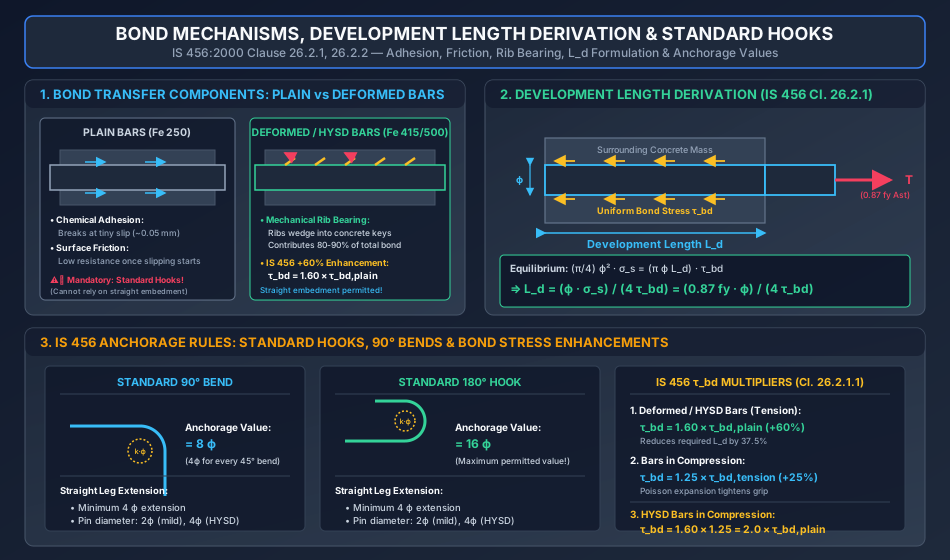
                          MECHANISMS OF BOND TRANSFER
                                       │
            ┌──────────────────────────┼──────────────────────────┐
            ▼                          ▼                          ▼
    CHEMICAL ADHESION               FRICTION               MECHANICAL RIB BEARING
 ┌─────────────────────┐    ┌─────────────────────┐    ┌─────────────────────────┐
 │ • Microscopic gum   │    │ • Activated after   │    │ • Transverse ribs bear  │
 │   effect of hydrated│    │   adhesion breaks   │    │   directly on concrete  │
 │   cement paste      │    │ • Roughness of bar  │    │ • Dominates in HYSD     │
 │ • Breaks at slip    │    │ • Confining pressure│    │ • 80-90% of total bond  │
 │   ~ 0.05 mm         │    │ • Wedging action    │    │ • Permits straight bars │
 └─────────────────────┘    └─────────────────────┘    └─────────────────────────┘
- Chemical Adhesion:
The natural microscopic adhesion between hydrated calcium silicate hydrate (C-S-H) gel and the oxide skin of the steel bar. While active initially at very low stress levels, chemical adhesion breaks down almost completely at negligible relative slip (). - Frictional Resistance:
After chemical adhesion breaks, gripping friction along the micro-rough steel surface resists further slip. Friction depends directly upon the transverse normal compressive pressure exerted by surrounding concrete shrinkage. In plain smooth round bars (Mild Steel Fe 250), friction and adhesion are the sole contributors to bond. - Mechanical Interlock (Bearing of Ribs):
In High Yield Strength Deformed (HYSD) bars (Fe 415, Fe 500, TMT bars), transverse ribs rolled onto the bar surface physically bear against the concrete "keys" formed between ribs.- This mechanical bearing constitutes to of the total bond capacity.
- Mechanical bearing generates outward radial bursting pressures in the concrete, tending to split the concrete cover longitudinally. Therefore, adequate concrete cover and confining transverse stirrups are essential to prevent splitting failure.
3. Flexural Bond vs Anchorage (Development) Bond
Historically, structural codes distinguished between two types of bond:
- Flexural Bond (Local Bond):
Arises along the length of a flexural member due to the rate of change of bending moment (). The tensile force in the longitudinal steel changes from section to section, generating a local interface shear stress: Where is the sum of perimeters of all tension bars, and is the flexural lever arm. In modern limit state design (IS 456:2000), explicit checks for local flexural bond are omitted because the development length and curtailment requirements comprehensively safeguard against flexural bond failure. - Anchorage Bond (Development Bond):
Refers to the average longitudinal bond stress developed over a finite embedment length required to develop the design yield stress in the bar, preventing pull-out or end slippage.
4. Mathematical Derivation of Development Length ()
Consider a straight reinforcing bar of diameter embedded in a concrete block, subjected to its full design tensile yield stress at the loaded end:
                            PULL-OUT EQUILIBRIUM MODEL
                                     L_d
                     ┌─────────────────────────────────┐
                     │ Concrete Mass                   │
                     │  τ_bd ◄──  τ_bd ◄──  τ_bd ◄──   │
                     ├─────────────────────────────────┼────────────► T = (π/4) ϕ² σ_s
                     │ Bar Diameter ϕ                  │
                     ├─────────────────────────────────┼────────────►
                     │  τ_bd ◄──  τ_bd ◄──  τ_bd ◄──   │
                     │                                 │
                     └─────────────────────────────────┘
-
Total Tensile Pull-Out Force ():
The total force tending to pull the bar out is the product of its cross-sectional area and the design steel stress:Under ultimate limit state conditions, . Thus:
-
Total Resisting Bond Force ():
The total bond force resisting pull-out acts uniformly along the cylindrical surface of the embedded bar of length :Let be the design bond stress between concrete and steel. The resisting force is:
-
Static Equilibrium Condition ():
Equating the applied tensile force to the resisting bond force: -
Solving for Development Length ():
Canceling and one from both sides:
Where:
- = Nominal diameter of the reinforcing bar ().
- = Stress in the bar at the section considered at design load ( for full yield development).
- = Design bond stress in concrete per IS 456 Clause 26.2.1.1 ().
5. Design Bond Stress () & Code Multipliers
5.1 Basic Design Bond Stress Values for Plain Bars in Tension (IS 456 Clause 26.2.1.1)
The basic values of design bond stress for plain mild steel bars (Fe 250) in tension are:
| Concrete Grade | M20 | M25 | M30 | M35 | M40 & above |
|---|---|---|---|---|---|
| Basic () | 1.20 | 1.40 | 1.50 | 1.70 | 1.90 |
5.2 Mandatory Code Enhancement Multipliers
1. Deformed / HYSD Bars in Tension (+60% Increase):
IS 456 Clause 26.2.1.1: "For deformed bars conforming to IS 1786 (Fe 415, Fe 500, Fe 550), these values shall be increased by 60 percent."
Consequence on : The required development length for HYSD bars is reduced by a factor of (a reduction compared to an imaginary plain bar of identical yield strength).
2. Bars in Compression (+25% Increase):
IS 456 Clause 26.2.1.1: "For bars in compression, the values of bond stress for bars in tension shall be increased by 25 percent."
Physical Explanation: In compression, longitudinal compressive stress causes lateral expansion of the steel bar due to Poisson's effect (). This wedging expansion exerts intense outward pressure against the concrete sleeve, significantly increasing frictional bond grip.
3. Combined Enhancement (HYSD Bars in Compression):
For HYSD bars located in compression zones:
The bond stress is exactly doubled relative to a plain bar in tension!
6. Anchoring of Reinforcement: Hooks & Bends (Clause 26.2.2)
When physical space within a structural element (such as an exterior column-beam joint or footing) is insufficient to accommodate the straight development length , the bar must be anchored using standard bends or hooks.
             STANDARD 90° BEND                              STANDARD 180° HOOK (U-HOOK)

         ────────────────────────┐                      ──────────────────────────┐
                                 │                                                │
                                 │                                                │
              Anchorage Value    │                           Anchorage Value      │
                  = 8 ϕ          │                               = 16 ϕ           │
                                 │                                                │
                                 ▼                                       ◄────────┘
                            (Extension ≥ 4ϕ)                          (Extension ≥ 4ϕ)
6.1 Anchorage Values of Bends & Hooks:
- Standard Bend:
The anchorage value of a standard bend is taken as (equivalent to for every deflection). - Standard Hook (U-Type Hook):
The anchorage value of a standard U-type hook is taken as (equivalent to ).
Upper Limit: The maximum anchorage value credited to any hook or bend is . - Mandatory Straight Extension:
Every standard bend or hook must terminate in a straight leg extension of at least . - Mandatory Minimum Mandrel Pin Diameters:
To prevent crushing and splitting of concrete on the inner radius of the bend:- For Mild Steel (Fe 250): Minimum inner mandrel diameter .
- For HYSD Bars (Fe 415, Fe 500): Minimum inner mandrel diameter (for ) and (for ).
- Plain vs Deformed Bar Usage:
- For plain mild steel bars in tension, standard hooks are mandatory at ends.
- For HYSD deformed bars, straight embedment without hooks is legally permitted provided the straight length accommodates .
7. Curtailment of Flexural Bars & The Support Condition
7.1 Extension Past Theoretical Cutoff Point (Clause 26.2.3.1)
When bending moment decreases along a span, some longitudinal bars may be stopped (curtailed) to economize steel.
- Theoretical Cutoff Point (TCP): The section where the moment capacity of the remaining continuous bars exactly equals the applied bending moment.
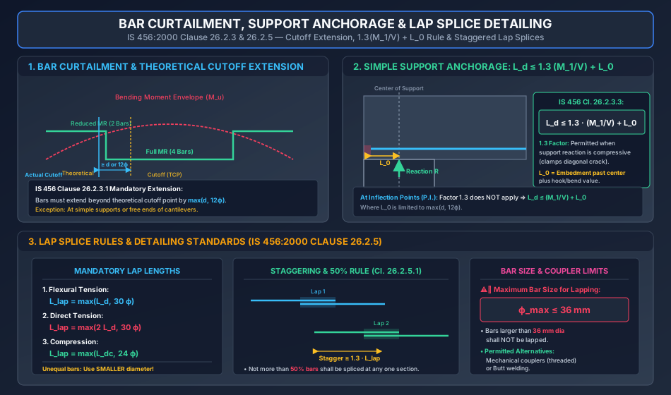
- Actual Cutoff Point (ACP): IS 456 Clause 26.2.3.1 mandates that bars must not be terminated at the TCP. They must extend beyond the TCP by a distance not less than: Where is effective depth and is bar diameter. (Exception: At simple supports and cantilever free ends).
7.2 Anchorage of Positive Moment Steel at Simple Supports (Clause 26.2.3.3)
At simple supports (and at points of inflection in continuous beams), the tensile reinforcement is subjected to simultaneous high shear force and low bending moment . To prevent anchorage pull-out before flexural capacity is developed, IS 456 enforces the renowned condition:
Where:
- = Development length of the tension bars continuing into the support ().
- = Moment of resistance of the section assuming all tension reinforcement at the section to be stressed to :
- = Factored shear force at the support section ().
- = Sum of anchorage length beyond the center of the support and equivalent anchorage value of any hook or bend. For straight embedment past the support center:
- The Enhancement Factor:
When the ends of the reinforcement are confined by a compressive reaction (such as a beam resting on a wall or column), the vertical compressive reaction clamps the concrete around the bars, suppressing diagonal splitting. IS 456 Clause 26.2.3.3 explicitly allows the ratio to be increased by (multiplied by )! - At Points of Inflection (P.I.):
At zero-moment inflection points, there is no compressive support reaction to clamp the bar. Therefore, the factor is dropped: Here, is restricted to .
8. Lap Splices & Mechanical Couplers (Clause 26.2.5)
When rebar lengths are insufficient to span an entire structural element, bars must be spliced. The most prevalent method is the lap splice, where two bars overlap over a specified distance to transfer stress through the intervening concrete.
                           LAP SPLICE OVERLAP & STAGGERING
                 │←─────────── L_lap ───────────→│
        ─────────┴───────────────────────────────┼─────────────────────────► Bar 1
                                                 │
                                                 │   Stagger Distance
                                                 │     ≥ 1.3 L_lap
                                                 ▼
        ─────────────────────────────────────────┬─────────────────────────► Bar 2
                                 │←─────────── L_lap ───────────→│
8.1 Required Lap Lengths () per IS 456 Clause 26.2.5.1
- Flexural Tension Lap: Where is the tensile development length.
- Direct Tension Lap (e.g. Water Tank Walls, Ties): Hooks must be provided at the ends of all bars spliced in direct tension.
- Compression Lap (e.g. Columns, Pedestals): Where is the compression development length ().
8.2 Critical Rules for Splicing:
- Unequal Bar Diameters: When bars of two different diameters and () are lapped, the lap length shall be calculated based on the smaller bar diameter ().
- Maximum Bar Diameter Limit ( Rule):
Lap splices shall not be used for bars larger than diameter. For bars , bars must be joined by:- Mechanical couplers (threaded or swaged sleeves).
- Thermit or electric arc butt welding. (Exception: In columns where bars are in compression, lap splicing is permitted only if additional spiral stirrups enclose the lap).
- Staggering of Splices (50% Rule):
Splices should be located away from sections of maximum bending moment.- Not more than of the tension bars shall be spliced at any one section.
- Spliced sections are considered staggered if the center-to-center distance between laps is not less than .
9. High-Precision Engineering Diagrams
9.1 Bond Transfer Mechanisms, L_d Derivation & Standard Hooks
The diagram below details the 3 microscopic bond mechanisms (adhesion, friction, rib bearing), the equilibrium free-body derivation of , standard bend () and hook () anchorage values, and IS 456 bond stress multipliers.
9.2 Bar Curtailment, Support Anchorage & Lap Splice Detailing
The diagram below details theoretical vs actual cutoff extensions, the simple support anchorage condition under compressive reactions, and staggered lap splice rules with the threshold.
10. Pre-Calculated Solved Numerical Examples
Problem 1: Development Length Multiples across Steel Grades and Bar Types (GATE CE / SSC JE)
Statement:
Calculate the development length in terms of bar diameter for concrete grade M25 () under the following conditions:
- Case A: Mild Steel (Fe 250, ) plain bar in tension.
- Case B: HYSD bar (Fe 415, ) deformed bar in tension.
- Case C: HYSD bar (Fe 415, ) deformed bar in compression.
- Case D: HYSD bar (Fe 500, ) deformed bar in tension.
Solution:
General formula:
Case A: Plain Fe 250 in Tension
Case B: HYSD Fe 415 in Tension (+60% Enhancement)
Case C: HYSD Fe 415 in Compression (+60% and +25% Enhancements)
Case D: HYSD Fe 500 in Tension (+60% Enhancement)
Summary Table for M25 Concrete:
| Case | Steel Grade | Stress State | Design () | Required |
|---|---|---|---|---|
| Case A | Fe 250 (Plain) | Tension | ||
| Case B | Fe 415 (HYSD) | Tension | ||
| Case C | Fe 415 (HYSD) | Compression | ||
| Case D | Fe 500 (HYSD) | Tension |
Problem 2: Verification of Bar Anchorage at Simple Support (UPSC ESE / GATE CE)
Statement:
A simply supported rectangular reinforced concrete beam has width and effective depth . Concrete is M25 and steel is Fe 415. At the support, the beam rests on a masonry wall of width . Clear end cover to bars is .
Two bars of diameter () continue straight into the support without hooks. The factored shear force at the support face is .
Check whether the straight bars satisfy the anchorage condition per IS 456:2000 Clause 26.2.3.3.
Step 1: Development Length of Fe 415 Bar in M25
Step 2: Moment of Resistance of Continuing Steel ()
Depth of neutral axis for 2 bars of continuing straight:
Check limiting depth: .
Since , section is under-reinforced.
Moment capacity :
Step 3: Embedment Length Past Center of Support ()
Step 4: Check IS 456 Anchorage Condition
Because the beam rests directly on a wall support, the reaction is compressive. The multiplier applies:
Step 5: Verification
Engineering Conclusion: The continuing straight bars are completely safe for anchorage. No 90° or 180° hooks are required at the simple support.
Problem 3: Design of Lap Splice for Unequal Bar Diameters (State AE / ESE)
Statement:
A reinforced concrete column cast with M25 concrete () and Fe 415 steel requires lapping of diameter bars from the lower story with diameter bars of the upper story.
Determine:
- The design lap length in compression.
- The design lap length if the member were in flexural tension.
- The minimum stagger distance between adjacent splices.
Solution:
Per IS 456 Clause 26.2.5.1, when bars of two different diameters are spliced, the lap length shall be calculated on the basis of the smaller bar diameter ().
1. Compression Lap Length:
For HYSD Fe 415 in compression with M25 concrete:
Code requirement:
Adopt a compression lap length of ().
2. Flexural Tension Lap Length:
For HYSD Fe 415 in tension:
Code requirement:
Adopt a tension lap length of ().
3. Minimum Stagger Distance:
Per IS 456 Clause 26.2.5.1:
Adopt a minimum center-to-center stagger distance of .
11. Comparative Analysis: Splice Types & Detailing Conditions
| Parameter | Flexural Tension Splice | Direct Tension Splice | Compression Splice |
|---|---|---|---|
| Typical Structural Member | Beams, Slabs (Flexural members) | Water tank cylindrical walls, Roof ties, Hangers | Columns, Compression chords of trusses |
| Governing Lap Length Formula | |||
| End Detail Requirement | Straight embedment allowed for HYSD bars | Hooks mandatory at both ends (even for HYSD) | Straight cuts allowed; square contact bearing |
| Max % of Bars Lapped at Section | (staggered by ) | (lapping avoided; couplers preferred) | (at any one floor level) |
| Maximum Bar Diameter for Lap | (couplers/welding if ) | ||
| Transverse Stirrup Binding | Normal stirrup spacing maintained | Closely spaced closed links required | Stirrups with pitch in lap |
12. Common Misconceptions & Exam Traps
[!WARNING]
Additive Multipliers Fallacy for HYSD in Compression:
A rampant misconception is adding percentage increases: .
This is completely incorrect. Multipliers are multiplicative:Unequal Bars Lap Diameter Selection:
When lapping a bar with a bar, students often incorrectly calculate the lap using the larger bar. IS 456 Clause 26.2.5.1 explicitly dictates: always use the smaller diameter ().The Simple Support 1.30 Factor Trap:
The factor applies only when the reaction introduces compressive stresses into the member end region (e.g., supported on a wall or column). At points of inflection or hanging supports, the factor is 1.00, not 1.30!Maximum Permissible Bar Size for Lapping ():
Questions frequently ask: "Can 40 mm diameter bars be lapped in a beam?"
Answer: No. Lap splices are forbidden for bars . They must be joined by welding or mechanical couplers.Counting Hook Anchorage toward in HYSD Bars:
Standard hooks in tension plain bars provide anchorage. However, for HYSD bars, full straight length is preferred; hooks in HYSD bars do not relieve the requirement for transverse confinement to prevent bursting.
13. Practice Questions for Self-Assessment
- GATE CE: Calculate the development length for an Fe 415 HYSD bar of diameter in tension embedded in M30 concrete ().
(Answer: ) - UPSC ESE: Why is the design bond stress increased by 25% for bars in compression compared to bars in tension?
(Answer: In compression, Poisson's lateral expansion wedges the steel tightly against the surrounding concrete core, increasing frictional resistance and suppressing crack widening). - SSC JE / State AE: What is the maximum anchorage value credited to a standard hook in a reinforcing bar?
(Answer: , where is the nominal bar diameter). - RRB JE: What is the maximum diameter of reinforcing bar that can be joined by a lap splice according to IS 456:2000?
(Answer: ).