Ductile Detailing of Reinforced Concrete Structures (IS 13920:2016 & SP 34)
In this chapter (3 topics)
On this page
- 1. Introduction & Philosophy of Ductile Detailing
- 2. General Requirements & Material Specifications (IS 13920:2016 Clause 5)
- 3. Ductile Detailing of Flexural Members (Beams) — Clause 6
- 3.1 Geometric Proportions (Clause 6.1)
- 3.2 Longitudinal Reinforcement Provisions (Clause 6.2)
- 3.3 Transverse Confinement Reinforcement (Clause 6.3)
- 4. Ductile Detailing of Compression Members (Columns) — Clause 7
- 4.1 Geometric Proportions (Clause 7.1)
- 4.2 Strong Column – Weak Beam Formulation (Clause 7.2.1)
- 4.3 Longitudinal Reinforcement in Columns (Clause 7.3)
- 4.4 Special Confining Transverse Reinforcement (Clause 7.4)
- 5. Beam-Column Joints and Special Shear Walls (Clauses 8 & 9)
- 5.1 Beam-Column Joint Confinement (Clause 8)
- 5.2 Special Structural Shear Walls (Clause 9)
- 6. Engineering Diagrams & Detailing Anatomy
- Diagram 1: Ductile Detailing of Beams and Confining Links
- Diagram 2: Column Confining Reinforcement, Joint Core & Spacing
- 7. Step-by-Step Design & Detailing Procedures
- 8. Pre-Calculated Solved Numerical Examples
- Example 1: Comprehensive Ductile Detailing of an RC Beam (IS 13920 Clause 6)
- Example 2: Column Special Confining Links (Ash) and Confining Length l0 Design
- Example 3: Strong Column – Weak Beam Joint Capacity Ratio Verification
- 9. Engineering Misconceptions & Site Detailing Pitfalls
- 10. Comparative Analysis: IS 456:2000 vs IS 13920:2016
- 11. Competitive Exam Traps & High-Yield Takeaways
- 12. Practice Questions & Exercises
- Question 1 (GATE CE)
- Question 2 (UPSC ESE)
- Question 3 (SSC JE / State AE)
1. Introduction & Philosophy of Ductile Detailing
In moderate to severe earthquake events (Seismic Zones III, IV, and V per IS 1893:2016), it is economically and practically unfeasible to design civil engineering structures to resist seismic inertial forces purely elastically. Instead, modern seismic design relies upon energy dissipation through inelastic cyclic deformation.
                               SEISMIC CAPACITY HIERARCHY
                                           │
         ┌─────────────────────────────────┴─────────────────────────────────┐
         ▼                                                                   ▼
  BRITTLE MODES (PREVENTED)                                         DUCTILE MODES (PROMOTED)
 ┌───────────────────────────────┐                                 ┌───────────────────────────────┐
 │ • Shear failure in beams/cols │                                 │ • Flexural yielding in beams  │
 │ • Anchorage / bond slip       │                                 │ • Core concrete confinement   │
 │ • Column storey mechanisms    │                                 │ • Controlled plastic hinge    │
 │ • Joint panel shear rupture   │                                 │   rotations at member ends    │
 └───────────────────────────────┘                                 └───────────────────────────────┘
The fundamental philosophy of IS 13920:2016 (Ductile Design and Detailing of Reinforced Concrete Structures Subjected to Seismic Forces) is grounded in Capacity Design:
- Ductility (): The structure must possess the ability to undergo large reversible inelastic displacements () without significant loss of lateral and vertical load-carrying capacity.
- Hierarchy of Strength: Brittle failure mechanisms (such as shear, bond failure, and joint failure) are designed to have a higher capacity than the ductile flexural yield mechanisms.
- Strong Column – Weak Beam Principle: Plastic hinges must form preferentially in the beams rather than in the columns, preventing catastrophic single-storey "soft-storey" sway collapse mechanisms.
- Concrete Confinement: Passive confining pressure from closed hoops with hooks prevents outer cover spalling from causing brittle core crushing and rebar outward buckling under high compressive strains.
2. General Requirements & Material Specifications (IS 13920:2016 Clause 5)
IS 13920:2016 stipulates mandatory minimum material grades and physical properties to ensure that the required plastic strain hardening develops prior to fracture:
┌─────────────────────────────────┬────────────────────────────────────────────────────────────────────────┐
│ Parameter                       │ Codal Requirement (IS 13920:2016 Cl. 5)                                │
├─────────────────────────────────┼────────────────────────────────────────────────────────────────────────┤
│ Minimum Concrete Grade          │ • Minimum M20 in all seismic zones (III, IV, V).                       │
│                                 │ • Minimum M25 for buildings > 15 m in height in Zones III, IV, V.       │
├─────────────────────────────────┼────────────────────────────────────────────────────────────────────────┤
│ Permissible Steel Grades        │ • Fe 415, Fe 500, Fe 550 (with "D" designation preferred, e.g., 500D). │
│                                 │ • Mild steel (Fe 250) permitted only if specially detailed.            │
├─────────────────────────────────┼────────────────────────────────────────────────────────────────────────┤
│ Minimum Elongation              │ • Minimum uniform elongation ≥ 14.5% to ensure large ductile rotation. │
├─────────────────────────────────┼────────────────────────────────────────────────────────────────────────┤
│ Actual vs Characteristic Yield  │ • Actual yield strength shall NOT exceed the specified characteristic  │
│                                 │   strength (f_y) by MORE THAN 20% (f_y,actual ≤ 1.20 f_y,nominal).     │
│                                 │   *Reason:* Over-strength beams can overload columns in shear/flexure. │
├─────────────────────────────────┼────────────────────────────────────────────────────────────────────────┤
│ Ultimate-to-Yield Ratio         │ • Actual ultimate tensile strength to actual yield strength ratio      │
│                                 │   (f_u / f_y) ≥ 1.15. Guarantees strain hardening capacity.            │
└─────────────────────────────────┴────────────────────────────────────────────────────────────────────────┘
[!IMPORTANT] Why is actual yield strength capped at ?
If an on-site rebar is excessively strong (e.g., Fe 415 bar having an actual yield of ), the beam's flexural capacity exceeds the design calculation. When an earthquake strikes, the beam fails to yield as intended; the unexpectedly high forces are transferred directly to columns and beam-column joints, potentially triggering brittle column shear failure!
3. Ductile Detailing of Flexural Members (Beams) — Clause 6
Flexural members are defined as structural components resisting primarily lateral seismic moments and transverse shear, with factored axial compressive stress (or ).
                               BEAM DUCTILE DETAILING RULES
                                             │
             ┌───────────────────────────────┼───────────────────────────────┐
             ▼                               ▼                               ▼
     GEOMETRIC LIMITS             LONGITUDINAL REBAR              TRANSVERSE HOOPS
 ┌─────────────────────────┐     ┌─────────────────────────┐     ┌─────────────────────────┐
 │ • b ≥ 200 mm            │     │ • pt,min = 0.24√fck/fy  │     │ • 135° hook with 10ϕ    │
 │ • b/D ≥ 0.30            │     │ • pt,max = 2.5%         │     │   extension (≥ 75 mm)   │
 │ • Span/D ≥ 4            │     │ • At joint:             │     │ • Confining zone: 2d    │
 │ • b ≤ bc + 2bw          │     │   Mu(+) ≥ 0.5 Mu(-)     │     │ • s ≤ min(d/4, 8ϕL,     │
 └─────────────────────────┘     │ • Span min: 25% of max  │     │   100 mm)               │
                                 └─────────────────────────┘     └─────────────────────────┘
3.1 Geometric Proportions (Clause 6.1)
- Clear span to effective depth ratio: . (Eliminates deep beam shear arch action).
- Beam width .
- Width-to-depth ratio: . (Prevents lateral torsional buckling during cyclic reversal).
- Beam width relative to supporting column: Beam width shall not exceed the column width plus on each side ( or strictly per detailed provisions).
3.2 Longitudinal Reinforcement Provisions (Clause 6.2)
- Minimum Reinforcement: At least two continuous longitudinal bars must be provided at both the top and bottom faces throughout the entire member span:
- Maximum Reinforcement: To ensure ductile under-reinforced section behavior and avoid bar crowding:
- Joint Face Reversal Resistance: In an earthquake, moments reverse dynamically. Under lateral sway, the bottom face at a joint undergoes compression during one half-cycle and tension during the next. Therefore:
- Midspan and Member-Length Steel: At any section along the beam length, both top and bottom steel areas must each be at least:
- Lap Splice Rules (Clause 6.2.6):
- Lap splices are strictly forbidden within:
- The beam-column joint.
- A distance of from the column face (the designated plastic hinge zone).
- Locations where analysis indicates flexural yielding under seismic combinations.
- Closed hoop stirrups must enclose the entire lap length at a maximum spacing of c/c.
- No more than 50% of the tension bars shall be spliced at any single cross-section.
- Lap splices are strictly forbidden within:
3.3 Transverse Confinement Reinforcement (Clause 6.3)
- Hoop Geometry: Stirrups must be closed hoops featuring a seismic hook with an extension of at least (and not less than ) embedded into the core concrete.
- Hoop Diameter: Minimum (or if clear span exceeds ).
- Special Confining Zone Length (): Over a length equal to from each support face and on either side of any potential plastic hinge zone: The first hoop must be installed within of the joint face.
- Intermediate Span Zone: Outside the confining zone, the hoop spacing must not exceed:
4. Ductile Detailing of Compression Members (Columns) — Clause 7
Columns are vertical elements resisting lateral seismic moments, transverse shear, and factored axial compressive loads exceeding .
4.1 Geometric Proportions (Clause 7.1)
- Minimum cross-sectional dimension: The minimum width or diameter shall not be less than (or of the largest longitudinal bar).
- Aspect ratio of cross-section: .
4.2 Strong Column – Weak Beam Formulation (Clause 7.2.1)
At every beam-column joint in a moment-resisting frame, the nominal flexural strength of the columns framing into the joint must exceed that of the beams by at least 40%:
Where:
- is the sum of nominal flexural strengths of columns above and below the joint, calculated at the factored axial load corresponding to the seismic load combination.
- is the sum of nominal flexural strengths of beams framing into the joint along the direction of interest.
       Column Upper
            │
            │ Mc,upper
            ▼
     ┌─────────────┐
◄─── │ Joint Panel │ ◄─── Mb,right
Mb,left└───────────┘
            ▲
            │ Mc,lower
            │
       Column Lower

     Requirement: (Mc,upper + Mc,lower) ≥ 1.4 · (Mb,left + Mb,right)
4.3 Longitudinal Reinforcement in Columns (Clause 7.3)
- Steel Percentage Limits: (Note: While IS 456 allows up to 6% in non-seismic zones, IS 13920 restricts to 4% to avoid extreme bar congestion and ensure concrete consolidation).
- Lap Splices (Clause 7.3.2):
- Lap splices must be located strictly in the central half of the clear column height ( to ).
- Splicing in the designated end confinement zone () is strictly prohibited.
- Lap length in tension.
- At most 50% of bars may be spliced at any single horizontal section.
- Closed hoops at spacing c/c must enclose the full splice length.
4.4 Special Confining Transverse Reinforcement (Clause 7.4)
When a column experiences severe cyclic bending, the outer concrete cover spalls away. Special confining reinforcement provides lateral triaxial confinement to the core, raising both ultimate compressive strength and strain capacity ().
                 COLUMN SPECIAL CONFINING ZONE EXTENT (l_0)
                                     │
           ┌─────────────────────────┼─────────────────────────┐
           ▼                         ▼                         ▼
   Largest dimension D       Clear height / 6             450 mm
        (D or B)                 (H_st / 6)             (Absolute Min)
 └───────────────────────┘ └───────────────────┘ └───────────────────────┘
                     l_0 = max[ D, H_st / 6, 450 mm ]
-
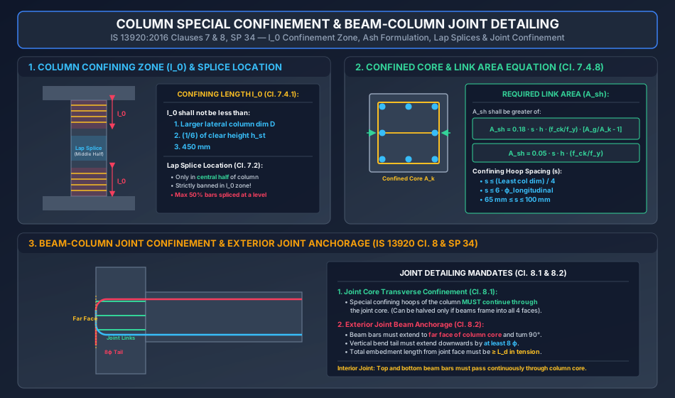
Confining Zone Length (): Confinement hoops must be provided over a length at both top and bottom ends of the column clear height:
-
Confining Hoop Spacing (): Within , the spacing of closed transverse ties shall satisfy:
(Note: The lower bound cap is , though is recommended for aggregate passage).
-
Required Area of Rectangular Confining Hoops ():
The total cross-sectional area of link legs in the direction of dimension must be at least the greater of:Where:
- = pitch / spacing of confining links ().
- = dimension of column core center-to-center of outer link legs in the direction under consideration ().
- = gross area of column cross-section ().
- = area of core concrete measured to the outer dimension of the confining links.
- = characteristic strengths of concrete and tie steel.
-
Spiral Confinement in Circular Columns:
The volumetric ratio of helical confinement steel must satisfy:
5. Beam-Column Joints and Special Shear Walls (Clauses 8 & 9)
5.1 Beam-Column Joint Confinement (Clause 8)
Beam-column joints represent critical shear transfer nodes. Joint failure is extremely brittle:
- Transverse Ties Through Joints: The special confining hoops of the column must continue through the beam-column joint unless beams frame into all four vertical faces of the joint and the beam width covers at least () of the column width on each face.
- Longitudinal Bar Anchorage:
In external beam-column joints, beam top and bottom bars must extend into the column core to a depth of beyond the column inner face, terminating in a standard bend pointing into the core with an extension tail length of at least .
5.2 Special Structural Shear Walls (Clause 9)
- Thickness: Minimum web thickness (or where boundary elements are required).
- Reinforcement Ratio: Minimum horizontal and vertical steel ratio () with maximum spacing . Two curtains of mesh are mandatory if .
- Boundary Elements: Boundary elements are heavily reinforced boundary columns provided at vertical edges when extreme-fibre compressive stress under factored seismic combinations exceeds:
6. Engineering Diagrams & Detailing Anatomy
Diagram 1: Ductile Detailing of Beams and Confining Links
The following engineering schematic illustrates the special confining zone, closed seismic hoops with tails, lap splice prohibition zones, and minimum span reinforcement.
       IS 13920:2016 DUCTILE BEAM ELEVATION AND DETAIL
 ┌─────────────────────────────────────────────────────────────┐
 │  Column Face                                   Column Face  │
 │  │◄── 2d Confining ──►│◄─ Span ─►│◄── 2d Confining ──►│     │
 │  │    s ≤ min(d/4,    │  s ≤ d/2 │    s ≤ min(d/4,    │     │
 │  │    8ϕL, 100 mm)    │          │    8ϕL, 100 mm)    │     │
 │  ├─┬─┬─┬─┬─┬─┬─┬─┬─┬─┬┼──┼───┼───┼┼─┬─┬─┬─┬─┬─┬─┬─┬─┬─┬┤     │
 │  │ │ │ │ │ │ │ │ │ │ ││  │   │   ││ │ │ │ │ │ │ │ │ │ │     │
 │  │◄──── Lap Splices Forbidden ──►│                          │
 │    First hoop ≤ 50 mm                                       │
 └─────────────────────────────────────────────────────────────┘
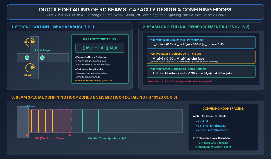
Diagram 2: Column Confining Reinforcement, Joint Core & Spacing
The following engineering schematic illustrates column confinement length , rectangular tie ties ( calculation), cross-tie engagement, and the beam-column joint pass-through detailing.
       IS 13920:2016 COLUMN & JOINT DUCTILE DETAILING
 ┌─────────────────────────────────────────────────────────────┐
 │  Joint Core: Column hoops continue through joint            │
 │  ───────────────────────────────────────────────            │
 │  │◄── Confining Zone l0 = max(D, Hst/6, 450 mm) ──►│        │
 │  │    s ≤ min(D/4, 6ϕL, 100 mm)                   │        │
 │  ├──┬──┬──┬──┬──┬──┬──┬──┬──┬──┬──┬──┬──┬──┬──┬───┤        │
 │                                                             │
 │  Central Half: Splicing Permitted (≤ 50% bars at section)   │
 │  Hoop spacing over lap ≤ 150 mm c/c                         │
 └─────────────────────────────────────────────────────────────┘
7. Step-by-Step Design & Detailing Procedures
                       SEISMIC DETAILING WORKFLOW (IS 13920)
                                         │
        ┌────────────────────────────────┴────────────────────────────────┐
        ▼                                                                 ▼
   BEAM WORKFLOW                                                   COLUMN WORKFLOW
 ┌───────────────────────────────────┐                           ┌───────────────────────────────────┐
 │ 1. Check geometry (b, b/D, L/d).  │                           │ 1. Check geometry (D ≥ 300, b/D). │
 │ 2. Compute pt,min & pt,max.       │                           │ 2. Check Strong Column - Weak Beam│
 │ 3. Verify Ast(+) ≥ 0.50 Ast(-).   │                           │    ΣMc ≥ 1.4 ΣMb.                 │
 │ 4. Verify span steel ≥ 0.25 max.  │                           │ 3. Check 0.8% ≤ ρc ≤ 4.0%.        │
 │ 5. Establish 2d confining zone.   │                           │ 4. Determine l0 = max(D,H/6,450). │
 │ 6. Detail hoops: s ≤ min(d/4,     │                           │ 5. Detail hoops: s ≤ min(D/4,     │
 │    8ϕL, 100 mm); 135° hooks.      │                           │    6ϕL, 100 mm).                  │
 │ 7. Check lap splices in midspan.  │                           │ 6. Calculate Ash (Eq A & B).      │
 └───────────────────────────────────┘                           └───────────────────────────────────┘
8. Pre-Calculated Solved Numerical Examples
Example 1: Comprehensive Ductile Detailing of an RC Beam (IS 13920 Clause 6)
Problem Statement:
An interior continuous RC beam of size and overall depth (effective depth , clear span ) is framed into RC columns in Seismic Zone IV. The material grades are concrete M25 () and steel Fe 415 (). At the face of the column, the top negative flexural design requires bars ().
Determine:
- Permissible minimum and maximum steel percentages ( and ) and corresponding areas.
- Minimum positive reinforcement required at the joint face.
- Minimum continuous reinforcement required throughout the top and bottom faces along the span.
- Extent and hoop spacing of the special confining reinforcement zone.
Solution:
Step 1: Check Section Geometry (Clause 6.1):
- Width OK.
- Ratio OK.
- Clear span to depth: OK.
Step 2: Minimum and Maximum Longitudinal Steel (Clause 6.2.1 & 6.2.2):
The negative joint steel provided is :
Since , the steel percentage is ductile and compliant.
Step 3: Minimum Positive Joint Steel (Clause 6.2.3): The positive (bottom) moment capacity at the joint face must be at least of the negative moment capacity:
Provide bars:
Step 4: Minimum Longitudinal Steel Throughout the Member Length (Clause 6.2.4): At every section along the top and bottom faces:
Also, must not be less than .
Therefore, the governing minimum continuous steel along the full span is . Providing bars () satisfies this throughout.
Step 5: Special Confining Hoop Reinforcement (Clause 6.3):
- Length of Confining Zone:
- Hoop Spacing () in Confining Zone:
Adopt 2-legged closed hoops with hooks at c/c.
The first hoop is located at from the column face. - Hoop Spacing Outside Confining Zone:
Example 2: Column Special Confining Links () and Confining Length Design
Problem Statement:
An interior square column of a multi-storey office building in Seismic Zone V has cross-sectional dimensions and a clear storey height (). The column is reinforced with longitudinal bars. The materials are concrete M30 () and steel Fe 500D (). Clear cover to outer links is .
Determine:
- The extent of the special confining zone .
- The maximum permissible spacing of the confining hoops.
- The required cross-sectional area of confining link legs () per hoop in each orthogonal direction.
- Verify if a rectangular outer hoop plus one cross-tie of bar (3 legs total) is adequate.
Solution:
Step 1: Extent of Confining Zone (Clause 7.4.1):
Hence, special confinement links must extend for from the beam bottom and beam top faces.
Step 2: Maximum Permissible Spacing (Clause 7.4.6):
Adopt spacing c/c.
Step 3: Core Dimensions and Gross Areas:
- Core dimension center-to-center of perimeter tie legs:
- Gross cross-sectional area:
- Core area (measured to outer dimension of ties):
Step 4: Calculation of Required Confining Steel Area (Clause 7.4.8): Evaluating Equation (A):
Evaluating Equation (B):
The governing required area is:
Step 5: Check Adequacy of Proposed 3 Legs of Links: With an outer closed hoop (2 legs) and one intermediate cross-tie (1 leg), the number of effective legs crossing any potential failure plane is :
Since , the arrangement is COMPLIANT AND SAFE.
Example 3: Strong Column – Weak Beam Joint Capacity Ratio Verification
Problem Statement:
At a beam-column framing joint in an intermediate storey of an unbraced frame, beams frame into the column from both left and right directions in the plane of lateral sway.
The design nominal flexural strengths of the beams at the joint faces are:
- Left Beam: (hogging moment capacity).
- Right Beam: (sagging moment capacity).
The upper column framing into the joint has a design flexural capacity under the concurrent factored axial load.
Determine the minimum required flexural capacity of the lower column () to satisfy the Strong Column – Weak Beam criterion of IS 13920:2016 Clause 7.2.1.
Solution:
Step 1: Compute Total Beam Flexural Resistance at the Joint:
Step 2: Apply the 1.4 Over-Strength Factor (Clause 7.2.1):
Step 3: Determine Required Lower Column Capacity:
Conclusion:
The lower column must provide a flexural strength of at least under the concurrent axial load. If it provides less, beam plastic hinges will not develop first, risking a story-mechanism collapse.
9. Engineering Misconceptions & Site Detailing Pitfalls
┌────────────────────────────────────────┬────────────────────────────────────────┬────────────────────────────────────────┐
│ Site Error / Detailing Defect          │ Engineering Consequence                │ IS 13920:2016 Mandatory Remedy         │
├────────────────────────────────────────┼────────────────────────────────────────┼────────────────────────────────────────┤
│ Using 90° Stirrup Hooks instead of     │ Under cyclic seismic shear and cover   │ 135° hooks with minimum 10ϕ            │
│ 135° seismic hooks                     │ spalling, 90° hooks open outward,      │ extension (≥ 75 mm) anchored into the   │
│                                        │ releasing core confinement entirely!   │ confined core concrete.                │
├────────────────────────────────────────┼────────────────────────────────────────┼────────────────────────────────────────┤
│ Splicing longitudinal bars inside      │ Plastic hinges undergo extreme cyclic  │ Splicing is strictly forbidden in 2d   │
│ the 2d plastic hinge zone of beams     │ yield strains, unzipping lap splices.  │ zones; locate splices near midspan.    │
├────────────────────────────────────────┼────────────────────────────────────────┼────────────────────────────────────────┤
│ Splicing column bars at storey floor   │ Maximum seismic column moments occur   │ Splices must be confined to the        │
│ levels (bottom of clear height)        │ at the column ends (within l0 zone).   │ central half of clear column height.   │
├────────────────────────────────────────┼────────────────────────────────────────┼────────────────────────────────────────┤
│ Omitting column ties through the       │ Brittle diagonal shear bursting of     │ Column confining hoops MUST pass       │
│ beam-column joint panel                │ unreinforced joint cores.              │ continuously through joint panels.     │
├────────────────────────────────────────┼────────────────────────────────────────┼────────────────────────────────────────┤
│ Using excessive longitudinal steel in  │ Beams become stronger than columns,    │ Enforce pt,max ≤ 2.5% in beams and     │
│ beams (over-reinforcing)               │ triggering catastrophic column hinges. │ ΣMc ≥ 1.4 ΣMb at all joints.           │
└────────────────────────────────────────┴────────────────────────────────────────┴────────────────────────────────────────┘
10. Comparative Analysis: IS 456:2000 vs IS 13920:2016
| Detailing Feature | Standard Detailing (IS 456:2000) | Ductile Seismic Detailing (IS 13920:2016) |
|---|---|---|
| Applicable Scope | Gravity loads, Wind, Seismic Zone II | Mandatory for Seismic Zones III, IV, and V |
| Minimum Concrete Grade | M20 for RCC | M20 generally; M25 for buildings in Zones III–V |
| Maximum Beam Steel () | () | () |
| Minimum Beam Steel () | ||
| Joint Face Positive Steel | Not quantified (often zero if no sag) | of joint face negative steel () |
| Transverse Stirrup Hooks | standard hooks permitted | closed seismic hooks with () tail |
| Confining Zone Length (Beams) | None mandated | from column support face |
| Confining Hoop Spacing (Beams) | in zone | |
| Column Minimum Dimension | (functional minimum) | (or ) |
| Column Splicing Zone | Anywhere (with transverse ties ) | Central half of clear height only; strictly forbidden in |
| Strong Column – Weak Beam | Not required | Mandatory: |
| Joint Confinement | Column ties omitted inside joint | Column ties must continue through joint |
11. Competitive Exam Traps & High-Yield Takeaways
[!CAUTION] GATE / ESE High-Yield Trap Checklist:
- Beam Confining Zone Length: It is (twice the effective depth), NOT and NOT .
- Beam Confining Hoop Spacing: The spacing limit is . Remember the factor for beams vs for columns!
- Column Confinement Length (): . It uses the clear storey height, not the center-to-center storey height.
- Column Confining Hoop Spacing: . Notice the factor is (tighter than beam's because column bars are in axial compression and buckle more readily).
- Actual vs Nominal Yield Strength: The actual yield strength must not exceed nominal by more than ().
- Strong Column Weak Beam Factor: The multiplier is (), NOT or .
- Splice Limits: No more than of bars can be spliced at a single section.
12. Practice Questions & Exercises
Question 1 (GATE CE)
In the ductile design of an RC frame per IS 13920:2016, an interior column of dimension with a clear height of is reinforced with longitudinal bars of diameter . The length of the special confining zone () from either end of the column and the maximum pitch of confining ties inside this zone are respectively:
- (A) and
- (B) and
- (C) and
- (D) and
Answer: (A)
Explanation:
.
Spacing .
Hence, and .
Question 2 (UPSC ESE)
Which of the following statements regarding the ductile detailing of beams per IS 13920:2016 are CORRECT?
- The web width of the beam shall not be less than .
- The width-to-depth ratio of the beam shall be greater than .
- Lap splices of flexural reinforcement are permitted within from the column face provided tie spacing is halved.
- Positive moment strength at the joint face must be at least of the negative moment strength.
- (A) 1, 2 and 3 only
- (B) 1, 2 and 4 only
- (C) 2, 3 and 4 only
- (D) 1, 3 and 4 only
Answer: (B)
Explanation:
Statement 3 is strictly FALSE. Lap splices are strictly prohibited within from the column face and within the beam-column joint under any circumstances. Statements 1, 2, and 4 are codal mandates per Clause 6.
Question 3 (SSC JE / State AE)
Per IS 13920:2016, the seismic hook of a closed hoop stirrup must have an angle of bend equal to:
- (A) with an extension of
- (B) with an extension of at least (and not less than )
- (C) with an extension of
- (D) with an extension of
Answer: (B)
Explanation:
Clause 6.3.1 mandates hooks with an extension of at least times the hoop bar diameter, but not less than , anchored deeply into the confined core concrete.