Design for Shear in Reinforced Concrete Beams
In this chapter (3 topics)
On this page
- 1. Introduction & Executive Summary
- 2. Mechanics of Shear Transfer in RC Beams
- 2.1 State of Stress in an Uncracked Homogeneous Elastic Beam
- 2.2 Crack Patterns in Reinforced Concrete Beams
- 2.3 Internal Shear Transfer Mechanisms in a Cracked Beam
- 3. Influence of Shear Span-to-Depth Ratio (av/d)
- 4. IS 456:2000 Design Philosophy and Provisions
- 4.1 Nominal Shear Stress (τv)
- 4.2 Design Shear Strength of Concrete without Web Steel (τc)
- 4.3 Maximum Permissible Shear Stress (τc,max) (Table 20)
- 5. Critical Section for Shear (IS 456 Clause 22.6.2)
- 6. Mathematical Derivations of Shear Reinforcement Capacity
- 6.1 Derivation for Vertical Stirrups (Vus)
- 6.2 Derivation for Inclined Stirrups (Angle α)
- 6.3 Derivation for Bent-Up Bars (Single or Group)
- 7. High-Precision Engineering Diagrams
- 7.1 Shear Failure Cracks, Internal Mechanisms & Critical Section
- 7.2 Shear Reinforcement Types, Truss Analogy & IS 456 Detailing Rules
- 8. Summary of IS 456 Design Cases
- Minimum Shear Reinforcement (Clause 26.5.1.6)
- Maximum Permissible Spacing (Clause 26.5.1.5)
- Side Face Reinforcement (Clause 26.5.1.3 & 26.5.1.7)
- 9. Pre-Calculated Solved Numerical Examples
- Problem 1: Standard Prismatic RC Beam Shear Design (GATE / ESE)
- Problem 2: Beam with Bent-Up Bars and 50% IS 456 Limitation (UPSC ESE / State AE)
- Problem 3: Haunched Beam of Varying Depth (GATE CE)
- 10. Comparative Analysis: Shear Failure Modes
- 11. Practical Detailing & Seismic Considerations (IS 13920:2016)
- 12. Common Misconceptions & Exam Traps
- 13. Practice Questions for Self-Assessment
1. Introduction & Executive Summary
In reinforced concrete (RC) flexural members, shear forces are always accompanied by bending moments. While flexural failures of under-reinforced sections are typically ductile—preceded by large deflections and wide, visible flexural cracks—shear failure is predominantly brittle, sudden, and catastrophic, often occurring without sufficient warning.
Consequently, the primary objective of structural concrete shear design under the Limit State Method (LSM) is to ensure that the shear capacity of any cross-section equals or exceeds its flexural capacity at all points, enforcing the fundamental engineering doctrine of capacity design: ductile flexural yielding must always precede brittle shear failure.
In IS 456:2000, the nominal shear stress is calculated and evaluated against two material thresholds:
- : The design shear strength of concrete without shear reinforcement (dependent on concrete grade and longitudinal tensile steel percentage ).
- : The maximum permissible shear stress beyond which brittle diagonal crushing of concrete compressive struts occurs, mandating section redesign.
2. Mechanics of Shear Transfer in RC Beams
2.1 State of Stress in an Uncracked Homogeneous Elastic Beam
In an uncracked beam, an infinitesimal stress element situated at depth from the neutral axis experiences a normal bending stress and a horizontal/vertical shear stress . The principal stresses are determined from Mohr's circle of stress:
The inclination of the principal planes with respect to the longitudinal beam axis is given by:
- At the Neutral Axis (): Flexural stress . Hence: The principal tensile stress equals and acts at an inclination of to the longitudinal axis. This inclined tensile stress is termed diagonal tension.
- At the Extreme Tension Fiber: Shear stress , and normal bending stress reaches its maximum tensile value. Thus , and cracks form purely vertically.
- Between the Neutral Axis and Extreme Fiber: Both and coexist. The trajectory of principal tensile stress forms a curved path that curves upward from the bottom fiber at and flattens toward as it crosses the neutral axis.
2.2 Crack Patterns in Reinforced Concrete Beams
Because concrete possesses high compressive strength but very low tensile strength (approximately ), cracks initiate perpendicularly to the trajectories of principal tensile stresses:
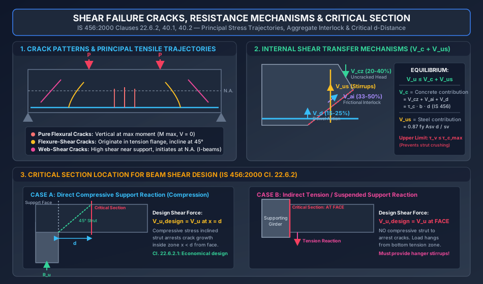
- Flexural Cracks (Vertical Cracks): Located near midspan where bending moment is high and shear force is low (). They initiate at the bottom tension face and propagate vertically toward the neutral axis.
- Flexure-Shear Cracks: The most common crack pattern in prismatic beams. They initiate as vertical flexural cracks near the quarter-span points where both and are significant. As they propagate upward into regions of increasing shear stress, they curve obliquely at roughly toward the compressive load point.
- Web-Shear Cracks: Observed primarily in thin-webbed sections (such as I-girders or flanged beams near supports) and prestressed concrete members where shear stress is extremely high and bending stress is minimal. These cracks initiate directly at the neutral axis at approximately and propagate diagonally before any flexural cracking occurs.
2.3 Internal Shear Transfer Mechanisms in a Cracked Beam
After diagonal tension cracking occurs, a beam without shear reinforcement cannot function as a homogeneous elastic element. The total internal shear resistance is transferred across the crack by four distinct physical mechanisms:
- Shear Resistance of Uncracked Concrete Compression Zone ():
The intact concrete head above the tip of the diagonal crack remains in a state of combined compression and shear. It carries approximately to of the total shear force. - Aggregate Interlock across Crack Surfaces ():
As the crack faces open and slide past one another, rough protruding coarse aggregates interlock, generating substantial tangential friction and interlock forces. This represents the largest single contributor, transferring to of total concrete shear resistance in normal aggregate concretes. (Note: in lightweight concrete or very high-strength concrete where cracks shear directly through aggregate particles, aggregate interlock is severely degraded). - Dowel Action of Longitudinal Reinforcement ():
The longitudinal tension bars crossing the diagonal crack resist transverse displacement analogous to dowel pins. This dowel action carries to of the shear force, supported by the concrete cover underneath. If the concrete cover splits horizontally along the bar line, dowel action drops abruptly to zero. - Shear Reinforcement ():
When web reinforcement (transverse stirrups or bent-up bars) is present, it directly bridges the diagonal crack, resisting opening displacements by tensile yielding (). Furthermore, stirrups physically restrain the longitudinal bars, preventing premature dowel splitting failure and holding the aggregate interlock surfaces tightly together.
3. Influence of Shear Span-to-Depth Ratio ()
The behavior and failure mode of an RC beam depend critically on the ratio of the shear span (distance between the point load and support) to the effective depth :
                       BEAM ACTION vs ARCH ACTION
   a_v/d < 1.0           1.0 ≤ a_v/d ≤ 2.8               a_v/d > 2.8
 ┌───────────────┐     ┌──────────────────────┐     ┌───────────────────────┐
 │   DEEP BEAM   │     │  SHORT / NORMAL BEAM │     │      SLENDER BEAM     │
 │  Arch Action  │     │ Shear-Compression /  │     │  Flexural-Shear Crack │
 │ Direct Strut  │     │   Diagonal Tension   │     │   True Beam Action    │
 └───────────────┘     └──────────────────────┘     └───────────────────────┘
- Slender Beams ():
True "beam action" dominates. Failure is initiated by flexure-shear cracking, followed by diagonal tension splitting. Linear strain distributions (Bernoulli-Euler hypothesis) are broadly applicable. - Intermediate Beams ():
Transition zone. After diagonal cracking, the beam can sustain additional load through redistributed internal arch action until the uncracked compression zone crushes in combined shear and compression (shear-compression failure). - Deep Beams ():
"Arch action" completely dominates. The applied concentrated load is transferred directly to the support by an inclined compression strut of concrete acting between the load point and the support reaction, with the longitudinal steel serving as a tie-rod (Strut-and-Tie Model). Beam theory is invalid; design must follow IS 456 Annex H or Strut-and-Tie Modeling.
4. IS 456:2000 Design Philosophy and Provisions
4.1 Nominal Shear Stress ()
Prismatic Beams of Uniform Depth (Clause 40.1)
Where:
- = Factored shear force at the design section ().
- = Breadth of the beam web (). (For flanged beams, ).
- = Effective depth of the beam ().
Beams of Varying Depth (Clause 40.1.1)
In haunched beams or tapered cantilevers where the effective depth varies along the span:
Where:
- = Factored bending moment occurring simultaneously with at the section ().
- = Angle between the top and bottom edges of the beam.
- Sign Convention (Critical Rule for Competitive Exams):
- Negative sign () is used when bending moment increases in the same direction in which the effective depth increases (favorable case: internal couple lever arm increases, generating a vertical component of compressive/tensile forces that opposes shear).
- Positive sign () is used when bending moment decreases in the direction of increasing depth (unfavorable case: vertical components add to the external shear force).
4.2 Design Shear Strength of Concrete without Web Steel ()
Per IS 456 Table 19, the design shear strength is an empirical function of:
- Grade of concrete (): Higher compressive strength improves tensile strength and aggregate interlock.
- Percentage of longitudinal tensile steel (): Higher tensile steel increases dowel action, restrains crack widening (enhancing aggregate interlock), and increases the depth of the compression zone (enhancing ).
The mathematical formula underlying Table 19 is:
Where:
Representative Values of () from IS 456 Table 19:
| M20 | M25 | M30 | M35 | M40 & above | |
|---|---|---|---|---|---|
| 0.28 | 0.29 | 0.29 | 0.29 | 0.30 | |
| 0.36 | 0.36 | 0.37 | 0.37 | 0.38 | |
| 0.48 | 0.49 | 0.50 | 0.50 | 0.51 | |
| 0.56 | 0.57 | 0.59 | 0.59 | 0.60 | |
| 0.62 | 0.64 | 0.66 | 0.67 | 0.68 | |
| 0.67 | 0.70 | 0.71 | 0.73 | 0.74 | |
| 0.82 | 0.85 | 0.87 | 0.90 | 0.92 |
Note: For flanged beams, is computed using the web width , i.e., .
Modification Factors for :
- Solid Slabs (Clause 40.2.1.1): For thin solid slabs, shear failure occurs under multi-axial constraint. The shear strength is increased by a factor :
- For overall slab depth , .
- For , .
- For , linear interpolation applies: .
- Members under Axial Compression () (Clause 40.2.2): Axial compression closes diagonal cracks and increases shear capacity:
- Members under Axial Tension () (Clause 40.2.2): Axial tension accelerates crack opening:
4.3 Maximum Permissible Shear Stress () (Table 20)
Regardless of the quantity of shear reinforcement provided, the nominal shear stress must never exceed . This upper limit prevents brittle diagonal compressive crushing of the concrete web struts before the transverse steel can yield:
| Concrete Grade | M15 | M20 | M25 | M30 | M35 | M40 & above |
|---|---|---|---|---|---|---|
| () | 2.5 | 2.8 | 3.1 | 3.5 | 3.7 | 4.0 |
Crucial Rule: If , increasing the stirrup steel is completely useless. The cross-sectional dimensions ( and/or ) or the concrete grade must be increased.
5. Critical Section for Shear (IS 456 Clause 22.6.2)
The design shear force is not necessarily the maximum shear force occurring at the center of the support. The location of the critical section depends on the support conditions:
        CASE A: DIRECT COMPRESSIVE SUPPORT                  CASE B: INDIRECT / SUSPENDED SUPPORT
        (Supported on Column or Wall)                      (Secondary Beam Framing into Main Girder)

         ↓↓↓↓↓↓ Factored Load                              ↓↓↓↓↓↓ Factored Load
      ══════════════════════════════════                 ══════════════════════════════════
     │                                  │               │                                  │
     │      Critical Section            │               │      Critical Section            │
     │       at distance d              │               │       at SUPPORT FACE            │
     │            ↓                     │               │            ↓                     │
     ├────────────┆─────────────────────┤               ├────────────┆─────────────────────┤
     │            ┆                     │               │            ┆                     │
     │ 45° Strut  ┆                     │               │ Tension    ┆                     │
     │  ┌──────┐  ┆                     │               │ Hanging    ┆                     │
     └──┴──────┴──┴─────────────────────┘               └──┬──────┬──┴─────────────────────┘
        │← d/2 →│                                          │Girder│
        Face of Support                                    └──────┘
- Direct Compressive Support (Clause 22.6.2.1):
When the reaction at the support introduces compressive stress into the end region of the beam (e.g., beam resting on a wall or framed monolithic into a column), an inclined concrete compressive strut forms at roughly from the support face. Any potential diagonal crack within this zone is clamped shut by the vertical compressive reaction.
Therefore, the critical section for shear is taken at a distance (effective depth) from the face of the support. The shear reinforcement designed for this critical section is continued uniformly into the support face. - Indirect Support / Hanging Load:
When the support reaction introduces tensile forces (e.g., when a secondary beam frames into the web of a primary girder, or when the load is applied at the bottom of the beam), no clamping compressive strut exists.
Therefore, the critical section is located directly at the face of the support, and specialized hanger reinforcement (closed stirrups) must be provided in the intersection zone to transfer the reaction upward into the compression zone.
6. Mathematical Derivations of Shear Reinforcement Capacity
                               MÖRSCH 45° TRUSS ANALOGY
                         Top Chord: Concrete Compression Zone
                 ┌──────────────────────────────────────────────────┐
                 │ C = M / z                                        │
                 └──┬─────────┬─────────┬─────────┬─────────┬───────┘
                    │        /│        /│        /│        /│
                    │       / │       / │       / │       / │
   Stirrup Tension  │      /  │      /  │      /  │      /  │ Concrete Strut
     Ties at 90°    │     /   │     /   │     /   │     /   │ Compression Diagonals
   T_v = 0.87 fy Asv│    / θ  │    /    │    /    │    /    │ at θ = 45°
                    │   /     │   /     │   /     │   /     │
                    │  /      │  /      │  /      │  /      │
                 ┌──┴─▼───────┴─▼───────┴─▼───────┴─▼───────┴─┐
                 │ T = M / z                                  │
                 └────────────────────────────────────────────┘
                        Bottom Chord: Tension Steel
                 │←   s_v   →│
                 │←─────── Horizontal Crack Projection = d ──────→│
6.1 Derivation for Vertical Stirrups ()
Consider a diagonal crack inclined at an angle to the horizontal axis of the beam.
- The horizontal projection of this crack across the effective depth is:
- Let the vertical stirrups be spaced at a uniform center-to-center spacing . The number of stirrups intercepted by the diagonal crack is:
- Each stirrup provides a cross-sectional area (equal to for an -legged stirrup). Under limit state conditions, the tensile stress in the stirrups reaches its design yield strength:
- The total tensile force developed in one stirrup is:
- Summing the tensile capacities of all stirrups crossing the crack gives the shear resistance :
6.2 Derivation for Inclined Stirrups (Angle )
If the stirrups are inclined at an angle to the longitudinal axis:
- The horizontal length over which stirrups intercept the crack is:
- The number of inclined stirrups crossing the crack is:
- Resolving the tensile capacity of each stirrup () in the vertical direction: Since :
6.3 Derivation for Bent-Up Bars (Single or Group)
When longitudinal tension bars are bent up at an angle (typically or ) at a single location:
- The bars intercept the diagonal crack directly.
- Resolving the bar tensile force vertically:
The Mandatory IS 456 50% Limitation (Clause 40.4.b):
In competitive examinations and practical design, this rule is paramount:
IS 456 Clause 40.4 (b): "Where bent-up bars are provided, their contribution to shear resistance shall not be taken more than half that of the total shear reinforcement ()."
The remaining (or more) of the shear force must be carried by vertical or inclined stirrups (). Bent-up bars alone can never be used as the sole shear reinforcement.
7. High-Precision Engineering Diagrams
7.1 Shear Failure Cracks, Internal Mechanisms & Critical Section
The diagram below details the principal stress trajectories, transition from vertical flexural cracks to inclined flexure-shear and web-shear cracks, the equilibrium of aggregate interlock and dowel action across crack surfaces, and the critical design section at distance from support.
7.2 Shear Reinforcement Types, Truss Analogy & IS 456 Detailing Rules
The diagram below details the 45° Mörsch truss model, the 3 types of shear reinforcement, the 50% capping rule for bent-up bars, and mandatory spacing and side-face reinforcement limits.

8. Summary of IS 456 Design Cases
                           SHEAR DESIGN DECISION TREE
                                 Evaluate τ_v
                                      │
            ┌─────────────────────────┴────────────────────────┐
            ▼                                                  ▼
     τ_v > τ_c,max                                       τ_v ≤ τ_c,max
    ┌───────────────┐                                   ┌──────────────┐
    │ REDESIGN BEAM │                                   │ Section Safe │
    │ Increase b, d │                                   │ From Strut   │
    │  or Concrete  │                                   │   Crushing   │
    └───────────────┘                                   └──────┬───────┘
                                                               │
                         ┌─────────────────────────────────────┴──────────────────┐
                         ▼                                                        ▼
                    τ_v ≤ τ_c                                                τ_v > τ_c
            ┌───────────────────────┐                                ┌─────────────────────────┐
            │ Provide Minimum Shear │                                │ Design Shear Steel for: │
            │     Reinforcement     │                                │  V_us = V_u - τ_c · b d │
            │  Asv/(b sv) ≥         │                                │  (Subject to s_v limits)│
            │  0.4 / (0.87 fy)      │                                └─────────────────────────┘
            └───────────────────────┘
- Case 1: : Section is inadequate. Danger of diagonal compression failure. Redesign cross-section.
- Case 2: : Concrete shear capacity is exceeded. Shear reinforcement must be designed to carry the excess shear: The calculated spacing must satisfy:
- Case 3: : Concrete alone can theoretically resist shear, but minimum shear reinforcement is legally mandatory for all beams to prevent sudden brittle collapse.
- Case 4: : Minimum shear reinforcement is still mandatory in beams (Clause 26.5.1.6). It is only exempt in members of minor structural importance, thin solid slabs, and footings.
Minimum Shear Reinforcement (Clause 26.5.1.6)
Maximum Permissible Spacing (Clause 26.5.1.5)
- For vertical stirrups: .
- For inclined stirrups (at ): .
Side Face Reinforcement (Clause 26.5.1.3 & 26.5.1.7)
In deep beams, diagonal tension cracks develop along the side faces of the web between the main tension steel and the compression zone.
- Trigger Conditions:
- Where the depth of the web in a beam exceeds (for flexure and shear).
- Where the overall depth exceeds when the member is subjected to torsion.
- Quantity: Total area of side-face reinforcement of the web area ().
- Distribution: Divided equally on the two lateral faces ( per face).
- Spacing: Spacing between side bars shall not exceed .
9. Pre-Calculated Solved Numerical Examples
Problem 1: Standard Prismatic RC Beam Shear Design (GATE / ESE)
Statement:
A reinforced concrete beam of rectangular section has a breadth , effective depth , and overall depth . The beam is reinforced with 4 bars of diameter () continuing straight into the support. At the critical section located at distance from the support face, the factored shear force is . The materials are concrete grade M25 () and steel grade Fe 415 ().
Design the vertical shear reinforcement using diameter 2-legged stirrups.
Step 1: Nominal Shear Stress ()
Step 2: Maximum Permissible Shear Stress ()
From IS 456:2000 Table 20, for M25 concrete:
Since , the cross-section is safe against diagonal compression crushing.
Step 3: Design Shear Strength of Concrete ()
Calculate percentage of longitudinal tensile reinforcement at the section:
From IS 456:2000 Table 19 for M25 concrete:
- At
- At
Using linear interpolation:
Step 4: Comparison & Determination of Shear to be Resisted
Since , shear reinforcement is mandatory to resist the net excess shear.
- Shear carried by concrete:
- Net factored shear to be carried by transverse stirrups:
Step 5: Design of 2-Legged 8 mm Stirrups
Area of 2-legged stirrups ():
-
Calculated Spacing for Strength ():
-
Spacing for Minimum Shear Reinforcement ():
-
Maximum Code Permissible Spacing ():
-
Governing Spacing:
Final Detailing Specification:
Provide 2-legged dia vertical stirrups @ center-to-center near the supports.
Problem 2: Beam with Bent-Up Bars and 50% IS 456 Limitation (UPSC ESE / State AE)
Statement:
An RC beam has breadth and effective depth . Concrete is M25 and steel is Fe 415. At midspan, the beam is reinforced with 6 bars of diameter. Towards the support, 2 of these bars are bent up at where bending moment is low, while 4 bars () continue straight into the support.
The factored shear force at the critical section is .
Calculate the shear resistance provided by the bent-up bars under IS 456 rules, and design the complementary 2-legged vertical stirrups required.
Step 1: Nominal Shear Stress ()
From Table 20, for M25: .
Since , section size is adequate.
Step 2: Concrete Shear Strength ()
Percentage of straight tension steel at the support:
From Table 19 for M25:
- At
- At
Interpolating:
Step 3: Total Shear to be Resisted by Steel ()
- Concrete shear resistance:
- Total excess shear:
Step 4: Capacity of Bent-Up Bars and 50% Rule
Two bars bent up at :
Nominal vertical capacity of the bent bars:
Application of IS 456 Clause 40.4 (b): The contribution of bent-up bars cannot exceed of the total shear reinforcement requirement :
Although the bent bars possess a capacity of , they are permitted to resist only .
Step 5: Design of Vertical Stirrups ()
The remaining shear must be resisted by vertical stirrups:
Using 2-legged stirrups:
- Calculated spacing:
- Minimum shear steel spacing:
- Maximum code spacing:
Final Specification:
Provide the 2 bent-up bars of dia at accompanied by 2-legged vertical stirrups @ c/c.
Problem 3: Haunched Beam of Varying Depth (GATE CE)
Statement:
A reinforced concrete beam of rectangular web width has a linearly varying effective depth. At a section , the effective depth is , and the slope of the haunch is . At this section, the factored shear force is and the factored bending moment is .
Calculate the nominal shear stress for:
- Case A: Bending moment increases in the direction of increasing depth .
- Case B: Bending moment decreases in the direction of increasing depth .
Solution:
Per IS 456:2000 Clause 40.1.1:
First evaluate the moment-haunch interaction term:
Case A: increases as increases (Favorable Case)
The negative sign applies:
Case B: decreases as increases (Unfavorable Case)
The positive sign applies:
Observation: Tapering depth in the direction of increasing moment reduces design shear stress by , demonstrating the structural efficiency of haunched frames.
10. Comparative Analysis: Shear Failure Modes
| Failure Mode | Typical Range | Concrete Grade & Web Type | Mechanism & Visual Characteristics | Prevention Strategy |
|---|---|---|---|---|
| Diagonal Tension Failure | Normal beams with thin webs, low web steel | Flexural crack inclines diagonally at 45° across the web, rapidly splitting the beam into two separate halves. Extremely brittle. | Provide adequate vertical stirrups crossing the crack (). | |
| Shear-Compression Failure | Short beams with moderate web reinforcement | Diagonal crack penetrates deep into the concrete head. The reduced uncracked concrete zone crushes under combined shear and compressive stresses. | Increase beam effective depth or concrete grade . | |
| Web Crushing Failure | Any, when | Heavily reinforced beams, thin I-webs | Inclined concrete struts between diagonal cracks crush under excessive diagonal compression before stirrups reach yield. | Redesign cross-section. Limit . |
| Dowel Splitting Failure | All | Beams with inadequate bottom cover or bar spacing | Horizontal splitting cracks develop along the longitudinal tension steel line due to upward dowel forces. | Provide vertical stirrups enclosing longitudinal bars; maintain minimum bottom/side cover. |
| Arch-Rib Failure | Deep beams, corbels, pile caps | Concrete arch strut crushes directly between concentrated load and support reaction plate. | Follow Strut-and-Tie model or IS 456 Annex H deep beam detailing. |
11. Practical Detailing & Seismic Considerations (IS 13920:2016)
- Stirrup Anchorage & Hook Bending:
Under severe earthquake shaking, concrete cover spalls away. If standard hooks are used, the stirrups open outward, completely destroying shear capacity and causing instantaneous column or beam collapse.- IS 13920:2016 mandates seismic hooks with an extension of at least (or ) embedded into the core concrete.
- First Stirrup Location:
The first stirrup from the face of any column or beam support must be placed at a distance of not more than from the support face. - Curtailment of Tension Reinforcement & Shear:
When longitudinal tension bars are terminated (curtailed) where no longer needed for flexure, the abrupt cessation of steel causes local stress concentrations that trigger premature diagonal cracks. IS 456 Clause 26.2.3.2 enforces strict shear checks at cut-off points: - Modern Site Preference:
While bent-up bars were historically favored to save steel, modern industrialized construction universally prefers pure vertical stirrups due to ease of fabrication, automated rebar tying, and elimination of cage congestion.
12. Common Misconceptions & Exam Traps
[!WARNING]
Over-Reinforcing for Shear when :
A common error in competitive exam problems is attempting to solve by decreasing stirrup spacing . No amount of stirrup reinforcement can prevent diagonal compression crushing of concrete. The section dimensions must be increased.Neglecting the 50% Rule for Bent-Up Bars:
In objective exams (GATE/ESE), questions frequently state: "A bent-up bar carries of shear, and total excess shear is . What shear must stirrups carry?"
Trap: Answering .
Correct: Bent-up bars cannot take more than of . Therefore, vertical stirrups must carry at least .Critical Section Distance Misapplication:
Using from the centerline of the support instead of the face of the support. For a wide column, the critical section is at from the centerline!Varying Depth Sign Error:
Remember: When and both increase simultaneously (e.g. at the support of a haunched continuous beam or cantilever), the internal forces produce a vertical upward component that opposes shear use minus sign ().Confusing Maximum Spacing with Minimum Steel:
Maximum spacing is . Minimum steel is . Both criteria must be satisfied independently, and the smaller spacing governs.
13. Practice Questions for Self-Assessment
- GATE CE: A rectangular reinforced concrete beam of width and effective depth is subjected to a factored shear force of . The concrete is M20 (, ) and longitudinal steel provides . Using Fe 415 steel and 2-legged stirrups, the required spacing is:
(Answer: ) - UPSC ESE: State four reasons why minimum shear reinforcement is mandatory in all reinforced concrete beams even when the factored shear stress is less than the concrete shear strength .
(Key points: sudden thermal/shrinkage cracking, dowel splitting restraint, holding cage in place during compaction, preventing catastrophic unheralded brittle collapse). - SSC JE / State AE: What is the maximum permissible spacing of vertical shear stirrups for an RC beam of effective depth ?
(Answer: ) - RRB JE: What is the maximum percentage of shear force that can be resisted by bent-up bars alone according to IS 456:2000?
(Answer: of the total shear reinforcement requirement )