Design of One-Way Slabs
In this chapter (3 topics)
On this page
- 1. Introduction & Structural Mechanics of One-Way Slabs
- 1.1 Fundamental Criteria for One-Way Action (Clause 24.1)
- 1.2 Mathematical Mechanics: Load Distribution via Grillage Analogy
- 2. Effective Span Provisions (Clause 22.2)
- 3. Flexural Design Formulation (Unit Strip Method)
- 3.1 Limiting Depth of Section (dreq)
- 3.2 Main Tension Reinforcement (Ast)
- 4. Reinforcement Rules & Codal Detailing Mandates
- 4.1 Minimum Reinforcement (Clause 26.5.2.1)
- 4.2 Maximum Bar Diameter (Clause 26.5.2.2)
- 4.3 Maximum Clear Spacing of Reinforcement (Clause 26.3.3b)
- 4.4 Purpose of Distribution Reinforcement
- 5. Shear Resistance in One-Way Slabs (Clause 40.2.1.1)
- 6. Continuous One-Way Slabs & Bending Moment Coefficients (Tables 12 & 13)
- 6.1 Bending Moment Coefficients (Table 12)
- 6.2 Shear Force Coefficients (Table 13)
- 7. Engineering Diagrams & Detailing Anatomy
- Diagram 1: One-Way Slab Behavior & 1-Meter Design Strip Idealization
- Diagram 2: One-Way Slab Reinforcement Detailing & Curtailment Rules
- 8. Step-by-Step Design Procedure for One-Way Slabs
- 9. Pre-Calculated Solved Numerical Examples
- Example 1: Comprehensive Design of a Simply Supported One-Way Slab
- Example 2: Continuous One-Way Slab Analysis per IS 456 Table 12 & Table 13
- Example 3: Cantilever Chhajja / Balcony Slab Design & Detailing
- 10. Engineering Misconceptions & Site Detailing Pitfalls
- 11. Comparative Analysis: One-Way Slabs vs Two-Way Slabs
- 12. Competitive Exam Traps & High-Yield Takeaways
- 13. Practice Questions & Exercises
- Question 1 (GATE CE)
- Question 2 (UPSC ESE)
- Question 3 (SSC JE)
1. Introduction & Structural Mechanics of One-Way Slabs
A slab is a two-dimensional planar structural element having an overall depth () that is very small compared to its span dimensions ( and ). Slabs serve as structural floors and roofs, transmitting transverse gravity and imposed surface loads directly to supporting beams, walls, or columns.
                           CLASSIFICATION BY ASPECT RATIO
                                         │
        ┌────────────────────────────────┴────────────────────────────────┐
        ▼                                                                 ▼
   ONE-WAY SLAB (Ly / Lx > 2.0)                                     TWO-WAY SLAB (Ly / Lx ≤ 2.0)
 ┌───────────────────────────────────┐                             ┌───────────────────────────────────┐
 │ • Bends primarily along short span│                             │ • Bends significantly along both  │
 │ • Cylindrical surface curvature   │                             │   orthogonal directions           │
 │ • Load path: >90% to long beams   │                             │ • Dishing / saucer curvature      │
 │ • Designed as 1-m wide strip beam │                             │ • Load shared between both pairs  │
 │ • Transverse steel: distribution  │                             │   of supporting beams/walls       │
 └───────────────────────────────────┘                             └───────────────────────────────────┘
1.1 Fundamental Criteria for One-Way Action (Clause 24.1)
A slab behaves and is designed as a one-way slab under either of two conditions:
- Aspect Ratio Threshold: When the slab is supported along all four edges by beams or masonry walls, but the ratio of the longer span () to the shorter span () exceeds 2.0:
- Two Opposite Edges Supported: Regardless of the aspect ratio, whenever a slab is supported on only two opposite parallel edges (with the other two edges entirely unsupported or free), all applied loads are constrained to span between those two supports.
1.2 Mathematical Mechanics: Load Distribution via Grillage Analogy
Consider an elastic slab carrying a uniformly distributed surface load . If modeled as two intersecting central orthogonal strips of unit width (Strip X of length and Strip Y of length ) carrying portions and respectively ():
Equating deflections at the central intersection point ():
When :
When :
Because more than of the total load is transferred along the shorter span , the bending moment along the long direction is negligible. Consequently, the slab deforms into a cylindrical surface, and can be accurately designed as an independent beam of unit width () spanning across .
2. Effective Span Provisions (Clause 22.2)
The design bending moments and shears depend upon the statutory effective span specified in IS 456:2000 Clause 22.2:
┌───────────────────────────────┬────────────────────────────────────────────────────────────────────────┐
│ Support Condition             │ Statutory Effective Span Formula (L_eff)                               │
├───────────────────────────────┼────────────────────────────────────────────────────────────────────────┤
│ Simply Supported (Cl. 22.2a)  │ L_eff = min[ (L_0 + d),  (L_0 + w) ]                                   │
│                               │ Where L_0 = clear span, d = effective depth, w = support width.        │
├───────────────────────────────┼────────────────────────────────────────────────────────────────────────┤
│ Continuous: w < L_0 / 12      │ L_eff = min[ (L_0 + d),  (L_0 + w) ]                                   │
│ (Narrow Supports, Cl. 22.2b1) │ Same as simply supported condition.                                    │
├───────────────────────────────┼────────────────────────────────────────────────────────────────────────┤
│ Continuous: w ≥ L_0 / 12      │ L_eff = L_0  (for clear span between rigid wide supports)               │
│ (Wide Supports, Cl. 22.2b2)   │ Or center-to-center if w < 600 mm, whichever is smaller.               │
├───────────────────────────────┼────────────────────────────────────────────────────────────────────────┤
│ Cantilever: Built into Wall   │ L_eff = L_0 + d / 2                                                    │
│ (Cl. 22.2c)                   │                                                                        │
├───────────────────────────────┼────────────────────────────────────────────────────────────────────────┤
│ Cantilever: Monolithic / Beam │ L_eff = L_0 + w / 2                                                    │
│ Continuous into support       │ Where w is the width of the supporting beam or column.                 │
└───────────────────────────────┴────────────────────────────────────────────────────────────────────────┘
3. Flexural Design Formulation (Unit Strip Method)
3.1 Limiting Depth of Section ()
For a 1-meter wide strip (), the section is designed as a balanced or under-reinforced rectangular beam. The minimum effective depth to resist the factored bending moment without compression reinforcement is:
Where values per IS 456:2000 are:
- Fe 250 (Mild Steel): ()
- Fe 415 (HYSD): ()
- Fe 500 (TMT): ()
[!NOTE] In practical slab design, deflection criteria (serviceability) almost always governs the choice of overall thickness (). Hence, the provided depth is considerably larger than , guaranteeing a significantly under-reinforced, highly ductile section ().
3.2 Main Tension Reinforcement ()
Using the IS 456 quadratic stress block relation:
Solving for required tensile area per 1-meter strip ():
Spacing of bars with diameter (individual bar area ):
4. Reinforcement Rules & Codal Detailing Mandates
                          STATUTORY SLAB REINFORCEMENT RULES
                                          │
        ┌─────────────────────────────────┼─────────────────────────────────┐
        ▼                                 ▼                                 ▼
   MINIMUM STEEL (Ast,min)        MAXIMUM BAR DIAMETER            MAXIMUM BAR SPACING
 ┌─────────────────────────┐     ┌─────────────────────────┐     ┌─────────────────────────┐
 │ • Mild Steel (Fe 250):  │     │ • ϕ_max ≤ D / 8         │     │ • Main Steel:           │
 │   0.15% b·D             │     │   (Cl. 26.5.2.2)        │     │   s ≤ min(3d, 300 mm)   │
 │ • HYSD (Fe 415/500):    │     │ • Example: For D=120 mm,│     │ • Distribution Steel:   │
 │   0.12% b·D             │     │   ϕ ≤ 15 mm (use ≤12 mm)│     │   s ≤ min(5d, 450 mm)   │
 │   (Cl. 26.5.2.1)        │     │                         │     │   (Cl. 26.3.3b)         │
 └─────────────────────────┘     └─────────────────────────┘     └─────────────────────────┘
4.1 Minimum Reinforcement (Clause 26.5.2.1)
To prevent sudden brittle rupture upon initial concrete cracking and control shrinkage/temperature strains:
Note: This minimum percentage applies to the gross total depth , not the effective depth .
4.2 Maximum Bar Diameter (Clause 26.5.2.2)
To maintain structural ductility and ensure adequate concrete surround:
Example: For a slab with , the maximum allowable rebar diameter is (use or bars).
4.3 Maximum Clear Spacing of Reinforcement (Clause 26.3.3b)
- Main Reinforcement (Short Span):
The horizontal pitch / spacing of main tension bars must not exceed: - Distribution / Secondary Reinforcement (Long Direction):
Distribution bars placed perpendicular to main steel must satisfy:
4.4 Purpose of Distribution Reinforcement
Although structural analysis assumes zero moment along the long span , distribution bars are mandatory in one-way slabs to:
- Resist tensile stresses induced by concrete shrinkage and daily temperature variations.
- Distribute concentrated point loads or wheel wheel patches laterally over a wider effective slab width ( per IS 456 Clause 24.3.2).
- Hold the main bottom reinforcement securely in position during concrete pouring and vibratory compaction.
5. Shear Resistance in One-Way Slabs (Clause 40.2.1.1)
Shear is rarely critical in slabs under uniformly distributed loads because the slab thickness provided for deflection control yields very low nominal shear stresses:
- Nominal Shear Stress:
- Permissible Shear Strength ():
Unlike beams, thin slabs benefit from multi-axial constraint and load dispersal. IS 456 Clause 40.2.1.1 enhances the design concrete shear strength (from Table 19) by a depth modification factor :
┌─────────────────────────┬───────┬───────┬───────┬───────┬───────┬───────┬────────────┐
│ Overall Depth D (mm)    │ ≤ 150 │  175  │  200  │  225  │  250  │  275  │ ≥ 300 mm   │
├─────────────────────────┼───────┼───────┼───────┼───────┼───────┼───────┼────────────┤
│ Slab Depth Factor (k)   │ 1.30  │ 1.25  │ 1.20  │ 1.15  │ 1.10  │ 1.05  │ 1.00       │
└─────────────────────────┴───────┴───────┴───────┴───────┴───────┴───────┴────────────┘
[!CRITICAL] Codal Mandate on Slab Shear Reinforcement:
In building slabs, shear stirrups are never provided. The cross-section must be sized such that:Under no circumstance may the nominal shear stress exceed half the maximum shear strength:
If , the slab depth must be increased.
6. Continuous One-Way Slabs & Bending Moment Coefficients (Tables 12 & 13)
For continuous one-way slabs spanning over three or more approximately equal spans (spans differing by of the longest span), IS 456 Clause 22.5.1 permits structural analysis using empirical moment and shear coefficients:
6.1 Bending Moment Coefficients (Table 12)
Where and .
┌───────────────────────────────────────┬──────────────────────────┬──────────────────────────┐
│ Location along Continuous Slab        │ Dead Load Coeff (α_d)    │ Imposed Load Coeff (α_l) │
├───────────────────────────────────────┼──────────────────────────┼──────────────────────────┤
│ At near middle of end span            │ + 1/12                   │ + 1/10                   │
├───────────────────────────────────────┼──────────────────────────┼──────────────────────────┤
│ At middle of interior span            │ + 1/16                   │ + 1/12                   │
├───────────────────────────────────────┼──────────────────────────┼──────────────────────────┤
│ At support next to end support        │ - 1/10                   │ - 1/9                    │
│ (First Interior Support)              │                          │                          │
├───────────────────────────────────────┼──────────────────────────┼──────────────────────────┤
│ At other interior supports            │ - 1/12                   │ - 1/9                    │
└───────────────────────────────────────┴──────────────────────────┴──────────────────────────┘
6.2 Shear Force Coefficients (Table 13)
┌───────────────────────────────────────┬──────────────────────────┬──────────────────────────┐
│ Location along Continuous Slab        │ Dead Load Coeff (β_d)    │ Imposed Load Coeff (β_l) │
├───────────────────────────────────────┼──────────────────────────┼──────────────────────────┤
│ At end support                        │ 0.40                     │ 0.45                     │
├───────────────────────────────────────┼──────────────────────────┼──────────────────────────┤
│ At first interior support (outer side)│ 0.60                     │ 0.60                     │
├───────────────────────────────────────┼──────────────────────────┼──────────────────────────┤
│ At first interior support (inner side)│ 0.55                     │ 0.60                     │
├───────────────────────────────────────┼──────────────────────────┼──────────────────────────┤
│ At other interior supports            │ 0.50                     │ 0.60                     │
└───────────────────────────────────────┴──────────────────────────┴──────────────────────────┘
7. Engineering Diagrams & Detailing Anatomy
Diagram 1: One-Way Slab Behavior & 1-Meter Design Strip Idealization
The schematic below illustrates the aspect ratio threshold (), cylindrical surface curvature, one-way load transfer to long edge beams, and the equivalent 1-meter wide strip beam model.
       ONE-WAY SLAB LOAD PATH & CYLINDRICAL CURVATURE
 ┌─────────────────────────────────────────────────────────────┐
 │  Long Edge Beam                               Long Edge Beam│
 │  ◄════════════════════════════════════════════════════════► │
 │  │                                                        │ │
 │  │      Load Transfer Arrows (Predominant Direction)      │ │
 │  │             ▲                              ▲           │ │
 │  │             │                              │           │ │
 │  │     ────────┼──────────────────────────────┼────────   │ │
 │  │             │  1-m Wide Design Strip       │           │ │
 │  │     ────────┼──────────────────────────────┼────────   │ │
 │  │             │                              │           │ │
 │  │             ▼                              ▼           │ │
 │  ◄════════════════════════════════════════════════════════► │
 └─────────────────────────────────────────────────────────────┘
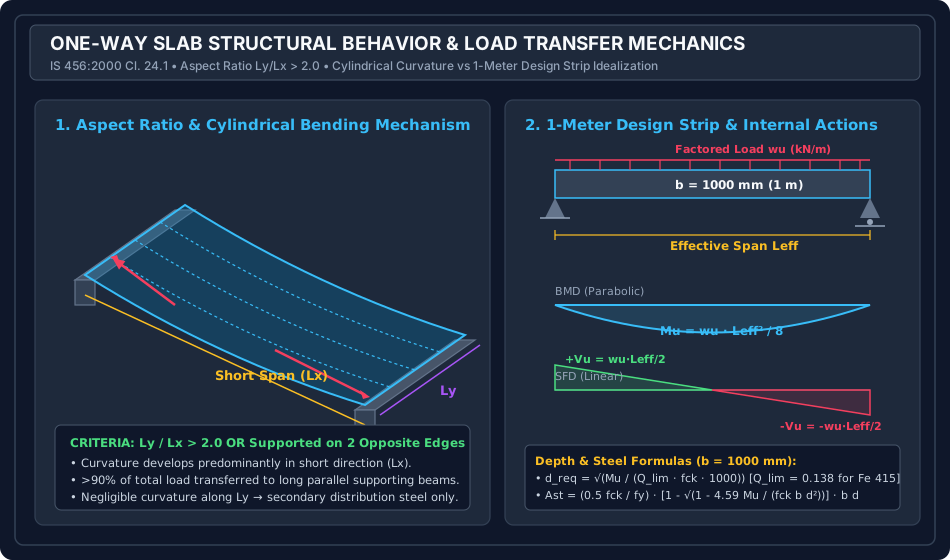
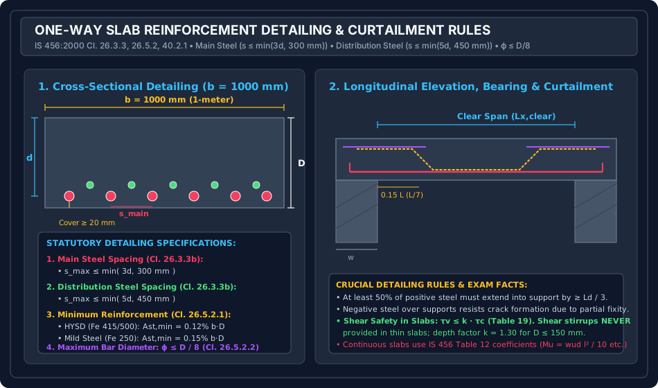
Diagram 2: One-Way Slab Reinforcement Detailing & Curtailment Rules
The schematic below illustrates the cross-sectional bar configuration, bottom main steel spacing limits (), top distribution steel spacing (), wall bearing anchorage, and bar cranking/curtailment.
       ONE-WAY SLAB REINFORCEMENT CROSS-SECTION & ELEVATION
 ┌─────────────────────────────────────────────────────────────┐
 │  Top Distribution Bars: s ≤ min(5d, 450 mm)                │
 │  ●       ●       ●       ●       ●       ●       ●       ●  │
 │  ═════════════════════════════════════════════════════════  │
 │  Bottom Main Bars: s ≤ min(3d, 300 mm); ϕ ≤ D/8            │
 │  ( )     ( )     ( )     ( )     ( )     ( )     ( )        │
 │  ─────────────────────────────────────────────────────────  │
 │  Clear Cover ≥ 20 mm (or 15 mm for bar diameter ≤ 12 mm)   │
 └─────────────────────────────────────────────────────────────┘
8. Step-by-Step Design Procedure for One-Way Slabs
                     ONE-WAY SLAB DESIGN WORKFLOW
                                   │
 ┌─────────────────────────────────┴─────────────────────────────────┐
 │ 1. Classify Slab: Verify Ly / Lx > 2.0 or 2-edge support.         │
 │ 2. Estimate Depth D: Based on deflection (L/d ≈ 25 - 30 for Fe415)│
 │    Compute effective depth d = D - c_nom - ϕ/2.                   │
 │ 3. Determine Effective Span (Leff): min(L0 + d, L0 + w).          │
 │ 4. Calculate Loads on 1-m Strip: Self-weight + Finishes + LL.     │
 │ 5. Compute Factored Mu & Vu: Mu = wu · Leff² / 8; Vu = wu · Leff/2│
 │ 6. Check Depth for Flexure: d ≥ √(Mu / (Q_lim · fck · 1000)).     │
 │ 7. Calculate Main Steel Ast & Spacing: s ≤ min(3d, 300 mm).       │
 │ 8. Design Distribution Steel: Ast,min = 0.12% b·D; s ≤ min(5d, 450)│
 │ 9. Check Shear Stress: τv = Vu / (b d) ≤ k · τc.                  │
 │ 10. Check Deflection: (L/d)_actual ≤ 20 · kt.                     │
 │ 11. Detail Reinforcement: Anchor ≥ 50% steel into supports (Ld/3).│
 └───────────────────────────────────────────────────────────────────┘
9. Pre-Calculated Solved Numerical Examples
Example 1: Comprehensive Design of a Simply Supported One-Way Slab
Problem Statement:
Design a simply supported reinforced concrete one-way roof slab spanning between two brick masonry walls having a clear span of . The longer dimension of the room is . The supporting walls are thick.
Design data:
- Live load (Imposed load) =
- Floor / Roof finish =
- Concrete grade = M20 ()
- Steel grade = Fe 415 ()
- Unit weight of reinforced concrete
Solution:
Step 1: Check Aspect Ratio:
Step 2: Trial Depth Selection from Deflection Control: For simply supported slabs, basic . For an assumed tension steel ratio , modification factor :
Adopting nominal clear cover and main bar diameter :
Provided effective depth:
Step 3: Effective Span (Clause 22.2a):
Step 4: Load Calculation per 1-Meter Wide Strip ():
- Self-weight of slab:
- Floor finishes:
- Imposed live load:
- Total service working load:
- Factored design load:
Step 5: Factored Bending Moment & Shear Force:
Step 6: Check Depth for Flexure: For Fe 415, :
Step 7: Main Tension Reinforcement ():
Minimum steel check (Clause 26.5.2.1):
Spacing of bars ():
Maximum allowable spacing:
Provide bars @ c/c:
Step 8: Distribution Reinforcement (HYSD ):
Spacing of bars ():
Maximum allowable spacing:
Provide bars @ c/c ().
Step 9: Check for Shear (Clause 40.2.1.1): Nominal shear stress:
For in M20 concrete (Table 19):
Depth factor for is :
Since , the slab is COMPLETELY SAFE IN SHEAR WITHOUT STIRRUPS.
Step 10: Check for Deflection Control (Clause 23.2.1):
For and , Figure 4 gives :
Example 2: Continuous One-Way Slab Analysis per IS 456 Table 12 & Table 13
Problem Statement:
A multi-panel floor system consists of continuous one-way slabs supported on parallel beams spaced at clear centers over 3 equal spans. The slab carries a characteristic dead load (including self-weight and finishes) of and an imposed live load of .
Using IS 456:2000 coefficients:
- Determine the factored design bending moment at the near middle of the end span, at the first interior support, and at the middle of the interior span.
- Determine the factored shear force at the outer face of the first interior support.
Solution:
Step 1: Factored Loads per 1-Meter Strip:
Span .
Step 2: Factored Bending Moments (Table 12):
- Near Middle of End Span:
- At First Interior Support:
- At Middle of Interior Span:
Step 3: Factored Shear Force at First Interior Support (Table 13): At the outer side of the first interior support, and :
Example 3: Cantilever Chhajja / Balcony Slab Design & Detailing
Problem Statement:
Design a cantilever chhajja (sunshade) slab having a clear projection of from a wide lintel beam. The live load is , finish is , and materials are concrete M20 () and steel Fe 415 (). To shed rainwater and reduce self-weight, the slab is tapered from at the root to at the free tip. Clear cover is .
Determine the required main top reinforcement and verify the section.
Solution:
Step 1: Effective Depth and Span: At the support:
Per Clause 22.2(c), for a cantilever built into a support:
Step 2: Load Calculation (Average Thickness):
- Self-weight:
- Live load + Finish:
- Total service load:
- Factored load:
Step 3: Factored Bending Moment & Shear:
Step 4: Main Reinforcement Calculation (Top Steel for Hogging):
Minimum steel check at support ():
Spacing of bars ():
Maximum allowable spacing:
Provide bars @ c/c as Top Main Steel ().
Anchorage: These top bars must be anchored into the lintel beam by at least full development length .
10. Engineering Misconceptions & Site Detailing Pitfalls
┌────────────────────────────────────────┬────────────────────────────────────────┬────────────────────────────────────────┐
│ Site Error / Detailing Defect          │ Engineering Consequence                │ IS 456:2000 Mandatory Remedy         │
├────────────────────────────────────────┼────────────────────────────────────────┼────────────────────────────────────────┤
│ Placing main reinforcement in the long │ Deflection and severe flexural         │ Main tension bars MUST always be       │
│ direction (Ly) instead of short (Lx)   │ cracking; slab collapses in flexure!   │ placed along the short span (Lx).      │
├────────────────────────────────────────┼────────────────────────────────────────┼────────────────────────────────────────┤
│ Omitting distribution steel in the     │ Uncontrolled thermal and shrinkage     │ Provide at least 0.12% bD (HYSD)       │
│ longitudinal direction                 │ cracks tear across the slab width.     │ distribution steel at s ≤ min(5d, 450).│
├────────────────────────────────────────┼────────────────────────────────────────┼────────────────────────────────────────┤
│ Walking on cantilever top rebar during │ Top steel gets pushed to the bottom;   │ Use rigid steel chair spacers to       │
│ concreting, displacing it downward     │ cantilever collapses upon form removal!│ preserve effective depth d at the top. │
├────────────────────────────────────────┼────────────────────────────────────────┼────────────────────────────────────────┤
│ Specifying shear stirrups in thin      │ Extreme bar crowding and honeycomb;   │ Slabs do not use shear stirrups;       │
│ one-way floor slabs                    │ impossible to pour and vibrate.        │ size depth so τv ≤ k · τc.             │
└────────────────────────────────────────┴────────────────────────────────────────┴────────────────────────────────────────┘
11. Comparative Analysis: One-Way Slabs vs Two-Way Slabs
| Feature | One-Way Slab | Two-Way Slab |
|---|---|---|
| Aspect Ratio Condition | (or supported on 2 edges) | (supported on 4 edges) |
| Deflection / Curvature Shape | Cylindrical curvature (bends along ) | Dishing / Saucer curvature (bends along both and ) |
| Load Sharing Mechanism | load transferred along short span | Load shared between both pairs of beams per Rankine-Grashoff / Annex D |
| Design Model | 1-meter wide strip beam across | Plate bending / Strip division (Middle & Edge strips) |
| Primary Reinforcement | Single layer along short span | Two orthogonal layers of main steel ( below, above) |
| Transverse Reinforcement | Nominal distribution steel () | Full flexural design steel in both directions |
| Corner Torsion Reinforcement | Not required | Mandatory at discontinuous corners ( in 4 layers) |
| Typical Thickness | Thicker () | Thinner () |
12. Competitive Exam Traps & High-Yield Takeaways
[!CAUTION] GATE / ESE High-Yield Trap Checklist:
- Grillage Analogy 4th-Power Law: Remember that load shared varies inversely with the 4th power of span: . At , exactly () load is carried in the short direction.
- Effective Depth of Cantilever: For a cantilever built into a wall, . For a cantilever forming the continuation of a beam, .
- Minimum Steel Gross vs Effective Depth: (uses gross depth , not effective depth !).
- Bar Diameter Limit: . For a slab, max bar size is (never use !).
- Maximum Spacing Limits:
- Main steel: .
- Distribution steel: .
- Shear Depth Factor : For , . For , . Stirrups are never used in slabs.
- Support Anchorage Rule: At least of positive flexural reinforcement must extend into supports by (Clause 26.2.3.3).
13. Practice Questions & Exercises
Question 1 (GATE CE)
A reinforced concrete slab of total depth is reinforced with high yield strength deformed bars (Fe 415). The minimum area of reinforcement per meter width and the maximum permissible diameter of the reinforcing bar are respectively:
- (A) and
- (B) and
- (C) and
- (D) and
Answer: (A)
Explanation:
For Fe 415, .
Maximum bar diameter .
Question 2 (UPSC ESE)
In a simply supported one-way slab of effective depth , the maximum clear spacing permitted by IS 456:2000 for the main flexural reinforcement and secondary distribution reinforcement respectively are:
- (A) and
- (B) and
- (C) and
- (D) and
Answer: (A)
Explanation:
Main reinforcement: .
Distribution reinforcement: .
Question 3 (SSC JE)
Per IS 456:2000, what is the value of the depth factor used to enhance the design shear strength of a reinforced concrete slab of overall depth ?
- (A)
- (B)
- (C)
- (D)
Answer: (D)
Explanation:
Per Clause 40.2.1.1, for slabs of overall depth , the depth factor .