Fundamentals of Prestressing, Systems & Materials
In this chapter (4 topics)
On this page
- 1. Introduction & Historical Evolution
- 2. Fundamental Principle & Analogy
- 2.1 Definition
- 2.2 Physical Analogies
- 3. Pre-Tensioning vs Post-Tensioning Systems
- 3.1 Pre-Tensioning System
- 3.2 Post-Tensioning System
- 3.3 Comparative Technical Matrix: Pre-Tensioning vs Post-Tensioning
- 4. Patented Prestressing Systems & Anchorage Hardware
- 4.1 Freyssinet System
- 4.2 Magnel-Blaton System
- 4.3 Gifford-Udall and CCL Systems
- 4.4 Macalloy System
- 4.5 BBRV System (Birkenmaier, Brandestini, Ros and Vogt)
- 5. High-Strength Materials: Physics of Prestress Retention
- 5.1 Why Mild Steel Fails Completely in Prestressing
- 5.2 High-Tensile Prestressing Steel Specifications (IS 1343:2012)
- 5.3 Stress-Strain Behavior of Prestressing Steel
- 5.4 Maximum Permissible Initial Jacking Stress (IS 1343:2012 Cl. 19.5.1)
- 6. High-Strength Concrete Requirements (IS 1343:2012)
- 6.1 Why High-Strength Concrete is Required
- 6.2 Minimum Concrete Grades per IS 1343:2012
- 6.3 Permissible Compressive Stresses in Concrete (IS 1343 Cl. 23.2.1)
- 6.4 Classification of Prestressed Concrete Structures (IS 1343:2012 Cl. 23.2.2)
- 7. Worked Numerical Examples with Complete Step-by-Step Verification
- Problem 1: Mathematical Proof of Why Mild Steel Fails in Prestressing
- Problem 2: Sizing of Prestressing Strands & Jacking Capacity (IS 1343:2012)
- Problem 3: Transfer Fiber Stresses & IS 1343 Member Classification
- 8. Construction Practices & Site Pitfalls
- 9. Competitive Examination Traps & Problem-Solving Shortcuts
- 10. Practice Problems & Examination Review Exercises
- Level 1: Objective Conceptual (SSC JE / RRB JE)
- Level 2: Multi-Concept Analytical (GATE CE)
- Level 3: Conventional Design Problem (UPSC ESE Mains)
- 11. Complete Topic Architecture & Upstream/Downstream Dependencies
- 12. Verification & Standards References
1. Introduction & Historical Evolution
Prestressed concrete represents one of the greatest engineering innovations of the twentieth century, transforming concrete from a material hampered by tensile weakness into a high-performance composite capable of spanning unprecedented distances with slender, crack-free profiles.
                         HISTORICAL EVOLUTION OF PRESTRESSING
                                         │
        1886 - 1907: Early Attempts (Failed)
        • P.H. Jackson (1886) & C.W. Doehring (1888): Initial patents using normal steel.
        • J. Mandl (1896) & M. Koenen (1907): Mild steel (fy = 250 N/mm²) stressed to ~140 N/mm².
        • FATE: Total failure! Concrete creep and shrinkage (~0.0008 strain) consumed
          100% of the initial strain, completely wiping out the prestress within months.
                                         │
                                         ▼
        1928: The Freyssinet Breakthrough (Birth of Modern Prestressing)
        • Eugène Freyssinet (France) discovered the rheological phenomenon of concrete creep (1926-1928).
        • Realized that only HIGH-TENSILE STEEL (fp > 1500 N/mm²) and HIGH-STRENGTH CONCRETE (≥ M40)
          could sustain prestress by retaining ~80% to 85% effective stress after all long-term losses.
                                         │
                                         ▼
        1938 - Present: Industrialization & Modern Standards
        • E. Hoyer (Germany, 1938): Long-line pre-tensioning using bond and the "Hoyer Effect".
        • Magnel-Blaton (Belgium), Gifford-Udall (UK), BBRV (Switzerland), Macalloy (UK).
        • Indian Standard: IS 1343:1980 evolved into IS 1343:2012 (Limit State Design Framework).
In conventional reinforced concrete (RCC), tensile cracks develop under normal service loads; concrete in the tensile zone below the neutral axis is considered structurally inactive except for holding the reinforcement in place and providing shear resistance. In contrast, prestressed concrete introduces a pre-determined internal compressive force that balances or eliminates tensile stresses caused by external gravity loads, allowing the entire concrete cross-section to participate actively in flexural resistance.
2. Fundamental Principle & Analogy
2.1 Definition
Prestressed Concrete: Concrete in which internal stresses are introduced in such magnitude and distribution that the tensile stresses resulting from external service loads are counteracted to a desired degree.
2.2 Physical Analogies
- The Wooden Barrel Analogy:
Wooden staves in a liquid barrel are clamped tightly by external tensioned metal hoops. The hoops introduce circumferential compression (hoop prestress) between the staves, preventing internal hydrostatic pressure from opening up gaps between them. - The Stack of Books Analogy:
A row of books placed horizontally cannot support its own weight without separating. However, if a person presses both ends inward with their hands (applying axial compressive prestress), the entire stack behaves as a rigid monolithic beam capable of supporting transverse loads across the span without sagging or opening joints.
3. Pre-Tensioning vs Post-Tensioning Systems
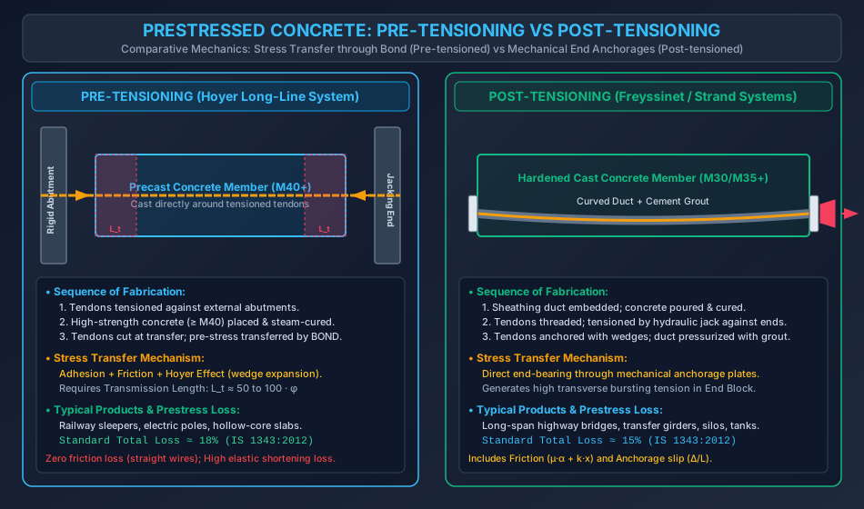
The fundamental classification of prestressed concrete is based on whether the prestressing steel is tensioned before or after the concrete has hardened:
3.1 Pre-Tensioning System
In pre-tensioning, tendons are stressed against external rigid abutments before the concrete is placed:
- High-tensile wires or strands are stretched between end anchorages on a long casting bed (up to ).
- Formwork is placed, and high-strength concrete () is poured directly around the tensioned steel and cured (often accelerated by steam curing).
- Once the concrete achieves its designated transfer strength (), the tendons are severed from the external abutments.
- As the cut tendons attempt to contract elastically, their contraction is restrained by adhesion, friction, and mechanical interlock with the surrounding hardened concrete.
- Prestress is transferred purely by BOND over a finite distance from the ends known as the transmission length ().
- Hoyer Effect: When the tendon is released, Poisson's ratio causes lateral expansion of the steel at the ends, wedging the tendon tightly into the concrete socket and dramatically increasing frictional bond resistance.
3.2 Post-Tensioning System
In post-tensioning, tendons are tensioned against the concrete after it has hardened:
- Sheathing ducts (corrugated HDPE or galvanized steel) containing unstressed tendons are placed inside the formwork along the desired cable trajectory (frequently parabolic).
- Concrete ( or ) is placed, compacted, and cured until achieving the specified transfer compressive strength.
- Hydraulic tensioning jacks bear directly against the hardened ends of the concrete member, stretching the tendons.
- The stretched tendons are anchored at the member ends using patented mechanical anchorages (wedges, split cones, or threaded nuts).
- Prestress is transferred directly through END BEARING onto the concrete via distribution bearing plates.
- The annular space between the tendon and the duct is injected with pressurized cement grout (bonded post-tensioning) to protect the steel against corrosion and establish strain compatibility.
3.3 Comparative Technical Matrix: Pre-Tensioning vs Post-Tensioning
| Structural / Operational Parameter | Pre-Tensioning System | Post-Tensioning System |
|---|---|---|
| Sequence of Tensioning | Tendon tensioned BEFORE placing concrete | Tendon tensioned AFTER concrete hardens |
| Transfer Mechanism | Pure BOND and Hoyer wedge effect | Mechanical END ANCHORAGE BEARING plates |
| Transmission Zone | Transmission length | Immediate transfer; requires End Block design for bursting tension |
| Tendon Trajectory | Usually straight; deflected tendons require hold-down devices | Easily profiled into parabolic, curved, or trapezoidal trajectories |
| Minimum Concrete Grade (IS 1343) | M40 (high bond strength required) | M30 (M35 for multi-strand systems) |
| Loss of Prestress | Typically (High elastic shortening, zero friction) | Typically (Low elastic shortening, friction + slip present) |
| Typical Structural Applications | Mass precast factory units: railway sleepers, electric poles, lintels | Long-span bridges, transfer girders, floor slabs, containment domes |
4. Patented Prestressing Systems & Anchorage Hardware
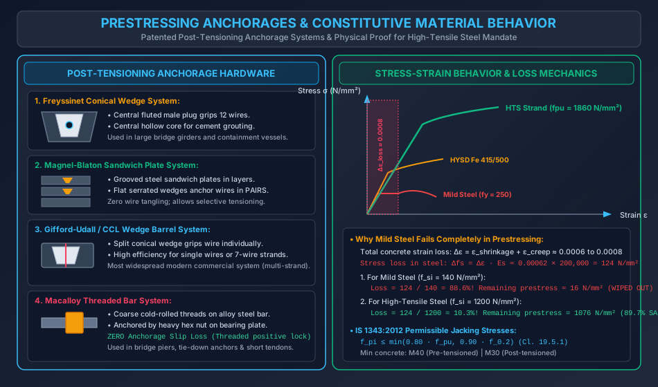
Several patented post-tensioning anchorages have been developed internationally and adopted under IS 1343:2012:
4.1 Freyssinet System
- Tendon Composition: Group of high-tensile wires (typically 8, 12, 18, or 24 wires of or diameter) arranged circularly inside a duct.
- Anchorage Mechanism: Consists of a heavily reinforced female conical cylinder (lined with high-tensile wire winding) cast into the concrete end block, and a fluted male conical plug made of concrete or steel.
- Jacking & Locking: A double-acting Freyssinet jack tensions all wires simultaneously with its primary ram, while the secondary inner ram rams the central male conical plug into the female cone, wedging the wires firmly between them.
- Grouting: A central axial hole in the male plug allows direct injection of high-pressure cementitious grout into the duct.
4.2 Magnel-Blaton System
- Tendon Composition: High-tensile wires ( to ) arranged in horizontal layers in rectangular ducts, separated by vertical and horizontal metal spacers.
- Anchorage Mechanism: Uses grooved high-carbon steel "sandwich plates" bearing against a heavy distribution base plate.
- Locking: Wires are tensioned in pairs using flat serrated steel wedges driven into the grooves of the sandwich plates.
- Advantage: Complete elimination of wire entanglement; allows gradual, symmetrical tensioning of wire pairs, minimizing sudden transfer shocks.
4.3 Gifford-Udall and CCL Systems
- Tendon Composition: Individual wires or -wire strands tensioned one by one.
- Anchorage Mechanism: High-strength steel cylindrical barrel with an internal tapered conical bore housing a two-piece or three-piece split conical wedge sleeve.
- Locking: As the tendon is pulled, the wedge sleeve bites into the steel wire; upon releasing the jack, the wedge is pulled into the tapered bore, locking the tendon instantly through wedge friction.
- Advantage: Lightweight single-wire jacks, exceptionally flexible for variable tendon sizes and site repairs.
4.4 Macalloy System
- Tendon Composition: High-strength silicon-manganese alloy steel bars of large diameter ( to ).
- Anchorage Mechanism: Coarse cold-rolled continuous threads on the bar ends engaged by heavy hexagonal anchor nuts bearing against thick steel distribution plates.
- Major Advantage: ZERO ANCHORAGE SLIP LOSS! Because the nut provides a positive mechanical screw lock, there is no draw-in wedge movement upon jack release.
- Applications: Vertical tie-down anchors, bridge pier prestressing, segmental bridge joint stitching.
4.5 BBRV System (Birkenmaier, Brandestini, Ros and Vogt)
- Tendon Composition: Multiple wires (up to 160 wires of or ).
- Anchorage Mechanism: Cold-formed "button heads" forged onto both ends of each wire, anchored in perforated cylindrical steel anchor heads with external threads and lock nuts.
5. High-Strength Materials: Physics of Prestress Retention
5.1 Why Mild Steel Fails Completely in Prestressing
The failure of all nineteenth-century attempts at prestressing was caused by the rheological properties of concrete: drying shrinkage and long-term creep.
Let the long-term strain loss in concrete due to shrinkage and creep be :
In typical structural concrete, . The corresponding stress loss in the prestressing steel is:
- Case A: Normal Mild Steel (): If mild steel is tensioned to its permissible working stress : The remaining effective prestress is only , which is completely wiped out by minor live load variations or temperature drops.
- Case B: High-Tensile Steel (): If high-tensile steel is tensioned to : The remaining effective prestress is ( of the prestress is retained indefinitely).
5.2 High-Tensile Prestressing Steel Specifications (IS 1343:2012)
Prestressing steel is available in four standard forms:
- Cold-Drawn Stress-Relieved Wires (IS 1785 Part 1 & 2): Plain or indented wires of diameters , with tensile strengths .
- High-Tensile Strands (IS 14268):
- -Wire Strand: Six outer helical wires spun tightly around a straight central king wire. Most common sizes: nominal diameter; characteristic strength (Class 1860, low relaxation).
- -Wire Strand: For massive post-tensioned bridge cables.
- High-Tensile Alloy Steel Bars (IS 2090): Smooth or cold-rolled threaded bars ( to ) with .
5.3 Stress-Strain Behavior of Prestressing Steel
Unlike mild steel, high-tensile steel exhibits no distinct yield point or yield plateau.
- The stress-strain curve departs smoothly from the proportional limit ().
- Design yield strength is defined by the Proof Stress () or the Total Extension Stress ():
- Modulus of Elasticity:
- Cold-drawn wires:
- Strands: (due to helical lay springiness)
5.4 Maximum Permissible Initial Jacking Stress (IS 1343:2012 Cl. 19.5.1)
The maximum stress to which a tendon may be tensioned at the jack shall not exceed:
For standard Class 1860 strands ():
- Hence, .
6. High-Strength Concrete Requirements (IS 1343:2012)
6.1 Why High-Strength Concrete is Required
- High Compressive Resistance: Resists massive concentrated prestressing forces at anchorages and extreme compressive bending stresses without excessive section dimensions.
- High Modulus of Elasticity (): Reduces instantaneous elastic shortening strain , minimizing initial prestress loss.
- Reduced Creep & Shrinkage: High-density concrete with low water-cement ratio () exhibits significantly lower creep coefficients and drying shrinkage.
- Superior Bond Strength: In pre-tensioned members, transfer relies entirely on bond shear along the transmission length. High tensile and bond strengths prevent slip.
- High Shear and Bearing Strength: Resists severe diagonal tension and bursting stresses in the anchorage zone.
6.2 Minimum Concrete Grades per IS 1343:2012
| System | Minimum Concrete Grade | Minimum Characteristic Strength () |
|---|---|---|
| Post-Tensioned Members | M30 (or M35 for multi-strand systems) | () |
| Pre-Tensioned Members | M40 |
6.3 Permissible Compressive Stresses in Concrete (IS 1343 Cl. 23.2.1)
- At Transfer (Temporary Stage under Prestress + Self-Weight):
- Extreme fiber compression: (or ), where is the cube strength at transfer ().
- At Service Loads (Design Working Stage):
- Extreme fiber compression: (or under peak transient loads).
6.4 Classification of Prestressed Concrete Structures (IS 1343:2012 Cl. 23.2.2)
Depending on the degree of prestress and permissible tensile stresses under working service loads, members are classified into three types:
                  IS 1343:2012 SERVICEABILITY CRACKING CLASSES
                                        │
         ┌──────────────────────────────┼──────────────────────────────┐
         ▼                              ▼                              ▼
      TYPE 1                         TYPE 2                         TYPE 3
  (Fully Prestressed)           (Moderately Prestressed)       (Partially Prestressed)
  • Tensile stress: ZERO        • Tensile stress allowed:      • Tensile cracks ALLOWED
    (σ_t ≤ 0)                     σ_t ≤ f_cr = 0.7√fck           under service loads.
  • Completely crack-free       • Concrete remains uncracked   • Crack width limited:
  • Containment vessels,          (no visible cracks)            w_max ≤ 0.1 mm (severe)
    nuclear reactors, bridges   • Standard road bridges          w_max ≤ 0.2 mm (moderate)
7. Worked Numerical Examples with Complete Step-by-Step Verification
Problem 1: Mathematical Proof of Why Mild Steel Fails in Prestressing
Statement:
A concrete beam of cross-section is prestressed with tendons located at the centroid of the section. The sustained compressive stress in the concrete at the level of the steel is . The shrinkage strain of the concrete is , the creep coefficient is , , and .
Compare the performance of:
(a) Mild steel wires tensioned to an initial stress of .
(b) High-tensile steel wires tensioned to an initial stress of .
Calculate the total stress loss, percentage loss, and remaining effective prestress in each case.
Solution:
Step 1: Calculate Concrete Creep Strain:
- The creep strain under sustained compressive stress :
Step 2: Total Time-Dependent Strain Loss:
- The total long-term strain loss experienced by the steel:
Step 3: Total Stress Loss in Steel:
- By Hooke's Law:
Step 4: Case (a) - Mild Steel ():
- Stress loss: .
- Percentage loss:
- Remaining effective prestress: (Observation: Over of the prestress is lost; the remaining is negligible. Mild steel is completely unusable for prestressed concrete).
Step 5: Case (b) - High-Tensile Steel ():
- Stress loss: .
- Percentage loss:
- Remaining effective prestress: (Observation: of the prestress is successfully retained indefinitely).
Problem 2: Sizing of Prestressing Strands & Jacking Capacity (IS 1343:2012)
Statement:
A post-tensioned bridge girder of cross-section requires an effective prestress force at the service stage after accounting for an estimated total prestress loss of . High-tensile -wire strands of nominal diameter (nominal cross-sectional area per strand, ) are to be used.
Determine:
(a) The required initial jacking force .
(b) The maximum permissible initial jacking stress per IS 1343:2012.
(c) The required number of strands and the actual jacking stress.
(d) The average concrete compressive stress at transfer and verify against the IS 1343 limit for M40 concrete ().
Solution:
Step 1: Required Initial Jacking Force ():
- Given effective prestress and loss ratio :
Step 2: Maximum Permissible Initial Jacking Stress ():
- Per IS 1343:2012 Cl. 19.5.1:
- Hence, the permissible initial jacking stress is:
Step 3: Number of Strands Required:
- Required total steel area:
- Number of strands ( each):
- Provided steel area:
- Actual initial jacking stress:
Step 4: Verification of Concrete Transfer Stress:
- Cross-sectional area of girder:
- Uniform compressive stress at transfer:
- Permissible compressive stress at transfer per IS 1343:
Problem 3: Transfer Fiber Stresses & IS 1343 Member Classification
Statement:
A simply supported prestressed concrete beam of rectangular cross-section spans . An initial prestressing force is applied with a constant eccentricity below the centroidal axis. Concrete grade is M40 (, unit weight ).
(a) Determine the top and bottom fiber stresses at midspan at transfer (under prestress + beam self-weight).
(b) If the beam is subjected to a superimposed service live load bending moment and total prestress losses are (), determine the top and bottom fiber stresses at service.
(c) Classify the member under IS 1343:2012 (Type 1, Type 2, or Type 3).
Solution:
Step 1: Section Properties & Self-Weight:
- Cross-sectional area:
- Section modulus (top and bottom are equal):
- Self-weight per unit length:
- Midspan bending moment due to self-weight:
Step 2: Component Stress Computations:
- Direct compressive stress due to prestress:
- Bending stress due to tendon eccentricity : (Causes compression at bottom fiber and tension at top fiber)
- Bending stress due to self-weight moment : (Causes compression at top fiber and tension at bottom fiber)
Step 3: Stresses at Midspan at Transfer (Prestress + Self-Weight):
- Top Fiber Stress:
- Bottom Fiber Stress: (Both fibers are in compression; zero tensile stress exists anywhere across the depth at transfer).
Step 4: Stresses at Midspan at Service Stage:
- Live load bending stress ():
- Total gravity moment stress:
- Effective prestress ratio (15% loss):
- Top Fiber Stress at Service:
- Bottom Fiber Stress at Service:
Step 5: Classification under IS 1343:2012:
- Under full service loads and maximum long-term losses, the bottom tensile zone stress is (still strictly in compression!).
- No tensile stress is induced in the member under working loads ().
- Therefore, this member is classified as TYPE 1 (Fully Prestressed, Crack-Free Member) under IS 1343:2012.
8. Construction Practices & Site Pitfalls
-
Grouting Delays in Post-Tensioned Ducts: Site Failure: Leaving tendons un-grouted inside ducts for weeks after tensioning in humid coastal climates. Consequence: Severe stress-corrosion cracking (SCC) and hydrogen embrittlement in the highly stressed () strands, leading to sudden catastrophic cable rupture. Remedy: Tendons must be pressure-grouted within 7 days of tensioning using approved expansive, non-shrink cement grout.
-
Jack Calibration & Friction Monitoring: Site Error: Relying solely on the hydraulic pressure gauge of the tensioning jack without cross-checking the physical cable elongation (). Code Rule (IS 1343): The measured tendon extension must agree with the calculated theoretical elongation within . If the discrepancy exceeds , tensioning must be halted immediately to investigate duct wobble or localized jamming.
-
Inadequate Concrete Compaction at Anchorage Zone: Site Error: Honeycombing and poor vibration around the heavily congested burst-reinforcement cages directly behind the bearing plates. Consequence: Punching shear and crushing blowout of the end block during jacking transfer. Remedy: Use self-compacting concrete (SCC) or micro-concrete with aggregate sizes in the end block region, vibrated with form vibrators.
-
Premature Prestress Transfer: Pitfall: Cutting pre-tensioning wires before concrete achieves its transfer strength ( or specified ). Consequence: Excessive transmission length, wire slip, and extensive bursting cracks at the member ends.
9. Competitive Examination Traps & Problem-Solving Shortcuts
-
The Minimum Concrete Grade Trap (GATE/ESE/SSC):
- Question asks: "What is the minimum grade of concrete for post-tensioned and pre-tensioned members respectively as per IS 1343:2012?"
- Pre-tensioned: M40 (often misremembered as M30).
- Post-tensioned: M30 (or M35 for multi-strand).
- Memory Trick: Pre-tensioning relies on BOND, requiring higher compressive and tensile strength M40 (higher number). Post-tensioning has mechanical anchorages M30.
-
Permissible Jacking Stress Trap (IS 1343 Cl. 19.5.1):
- Maximum initial jacking stress is governed by the lesser of and .
- For strands where , .
- Hence, often governs over .
-
Loss Comparison Trap (Pre vs Post-Tensioning):
- Pre-tensioning: Zero friction loss (straight tendons on bed), but highest elastic shortening loss (tendons cut after concrete cast).
- Post-tensioning: Friction and anchorage slip losses are present, but elastic shortening is zero if all tendons are tensioned simultaneously! If tensioned sequentially, average elastic shortening loss is half.
-
Serviceability Types Trap (IS 1343:2012):
- Type 1: Tensile stress (No tension).
- Type 2: Tensile stress (Tension allowed, but NO cracks).
- Type 3: Cracks allowed, but crack width .
10. Practice Problems & Examination Review Exercises
Level 1: Objective Conceptual (SSC JE / RRB JE)
-
In a pre-tensioned concrete member, the prestressing force is transferred to the concrete by:
- (A) Bearing plates at the ends
- (B) Bond and friction along the transmission length
- (C) End nuts and anchor sleeves
- (D) Shear connectors along the top flange
Answer: (B)
-
As per IS 1343:2012, the minimum grade of concrete permitted for pre-tensioned construction is:
- (A) M25
- (B) M30
- (C) M35
- (D) M40
Answer: (D)
-
Which patented post-tensioning system utilizes coarse cold-rolled threaded alloy steel bars with hex nuts?
- (A) Freyssinet
- (B) Magnel-Blaton
- (C) Macalloy
- (D) Gifford-Udall
Answer: (C)
-
A prestressed concrete member in which tensile stresses are permitted under service loads up to without cracking is designated as:
- (A) Type 1
- (B) Type 2
- (C) Type 3
- (D) Non-prestressed
Answer: (B)
Level 2: Multi-Concept Analytical (GATE CE)
- A high-tensile wire of diameter is tensioned to an initial stress of in a pre-tensioned beam. The concrete experiences a shrinkage strain of and a creep strain of . Taking , the percentage loss of prestress due to shrinkage and creep combined is:
- (A)
- (B)
- (C)
- (D)
Solution: Total strain loss .
Stress loss .
. Correct choice is (A).
Level 3: Conventional Design Problem (UPSC ESE Mains)
- A post-tensioned prestressed concrete beam of rectangular section supports a superimposed service live load of over an effective span of . (a) Calculate the minimum prestressing force required at an eccentricity of below the centroid to satisfy Type 1 crack-free criteria at midspan (assuming total prestress loss and concrete density ). (b) Verify the compressive stresses at transfer and service against IS 1343:2012 permissible limits for M45 concrete. (c) Detail the end block hardware and anchorage configuration for the proposed cable layout.
11. Complete Topic Architecture & Upstream/Downstream Dependencies
                       REINFORCED & PRESTRESSED CONCRETE
                                     │
           ┌─────────────────────────┴─────────────────────────┐
           ▼                                                   ▼
Chapter 09: Design of Water Tanks                   Chapter 10: Prestressed Concrete
(IS 3370:2021 Limit States)                         (IS 1343:2012)
                                                               │
           ┌───────────────────────────────────────────────────┼───────────────────────────────────┐
           ▼                                                   ▼                                   ▼
Topic 10-01: Fundamentals & Systems                Topic 10-02: Losses of Prestress    Topic 10-03: Analysis & Design
(Pre vs Post-tensioning, Materials,                 (Elastic, Creep, Shrinkage,         (Stress, Internal Couple,
 Anchorages: Freyssinet, Magnel, Macalloy)           Relaxation, Friction, Slip)         Load Balancing Concepts)
                                                                                                   │
                                                                                                   ▼
                                                                                       Topic 10-04: End Block Design
                                                                                       (Anchorage Bursting, Guyon/Magnel)
- Upstream Dependencies:
SOM-01-01&SOM-01-02: Hooke's Law, constitutive stress-strain curves, modulus of elasticity.RCC-01-01toRCC-01-03: Concrete compressive strength, modular ratio, creep, and shrinkage.
- Downstream Dependencies:
RCC-10-02: Direct formulation of each individual loss mechanism using materials and systems established here.RCC-10-03: Flexural stress computations and load balancing profiles across Type 1, 2, and 3 members.RCC-10-04: End block bursting force design directly governed by post-tensioning anchorage bearing plates.
12. Verification & Standards References
- Bureau of Indian Standards:
- IS 1343: 2012 – Prestressed Concrete - Code of Practice (Second Revision).
- IS 1785 (Part 1 & 2): 1983 (Reaffirmed 2018) – Plain Hard-Drawn Steel Wire for Prestressed Concrete.
- IS 14268: 2022 – Uncoated Stress Relieved Low Relaxation Seven-Ply Strand for Prestressed Concrete - Specification.
- IS 2090: 1983 (Reaffirmed 2018) – High Tensile Steel Bars for Prestressed Concrete.
- IS 456: 2000 (Reaffirmed 2021) – Plain and Reinforced Concrete - Code of Practice.
- Core Textbooks & Reference Manuals:
- Krishna Raju, N., Prestressed Concrete, 6th Edition, Tata McGraw-Hill Education.
- Lin, T.Y., and Burns, N.H., Design of Prestressed Concrete Structures, 3rd Edition, John Wiley & Sons.
- Collins, M.P., and Mitchell, D., Prestressed Concrete Structures, Prentice Hall.