Modern Surveying, GNSS/GPS, Aerial Photogrammetry & Remote Sensing/GIS
In this chapter (1 topics)
On this page
- 1. Module Overview & Pedagogical Scope
- 2. Learning Objectives & Exam Weightage Analysis
- Learning Objectives
- Exam Weightage Analysis
- 3. Electronic Distance Measurement (EDM) & Total Station Architecture
- 3.1 Classification of EDM Instruments
- 3.2 Total Station Components
- 4. Wave Propagation, Phase Shift Equations & Atmospheric PPM Corrections
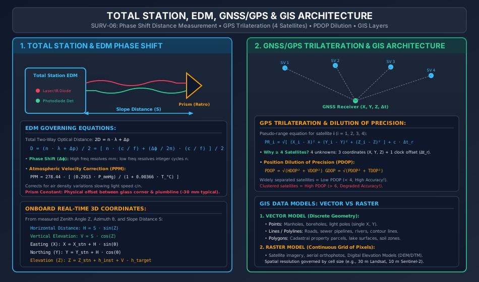
- 4.1 Phase Shift Principle of Distance Measurement
- 4.2 Atmospheric Velocity Correction (Parts Per Million - PPM)
- 5. Global Navigation Satellite Systems (GNSS / GPS / NavIC)
- 5.1 The Three Structural Segments
- 5.2 Pseudo-Range Trilateration (Why 4 Satellites?)
- 6. GPS Dilution of Precision (DOP) & Differential Techniques
- 6.1 Geometric Dilution of Precision (GDOP)
- 6.2 Differential GPS (DGPS) and Real-Time Kinematic (RTK)
- 7. Aerial Photogrammetry: Camera Optics, Geometry & Scale Formulations
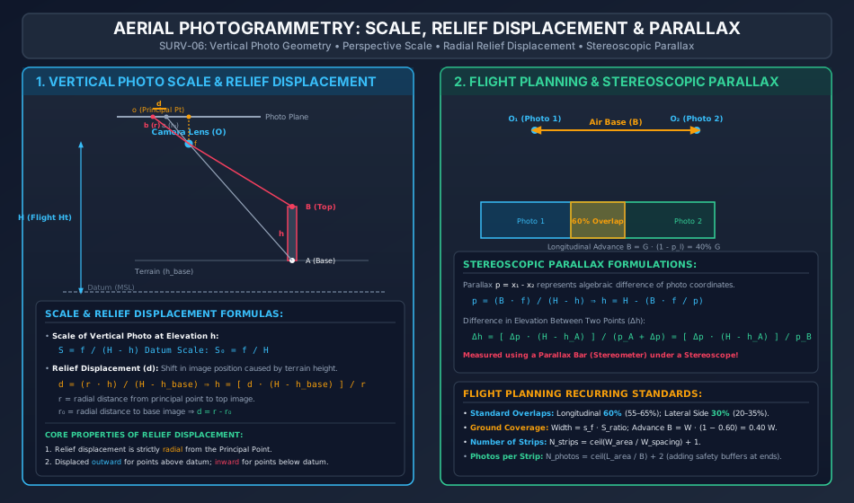
- 7.1 Geometry of Vertical Aerial Photographs
- 7.2 Scale of a Vertical Photograph
- 8. Relief Displacement Analytical Derivation & Structural Height Estimation
- 8.1 Definition & Mathematical Derivation
- 8.2 Determining Object Height (h)
- 8.3 Inviolable Characteristics of Relief Displacement
- 9. Stereoscopic Vision, Flight Strip Overlaps & Parallax Equations
- 9.1 Overlap Criteria for Flight Planning
- 9.2 Flight Planning Formulations
- 9.3 Stereoscopic Parallax Equations
- 10. Remote Sensing Principles & GIS Data Architectures
- 10.1 Spectral Reflectance Curves
- 10.2 Normalized Difference Vegetation Index (NDVI)
- 10.3 GIS Vector vs Raster Data Models
- 11. Step-by-Step Rigorous Worked Numerical Examples
- Problem 1: Complete Aerial Flight Planning & Photo Count
- Problem 2: Structural Height from Relief Displacement
- Problem 3: Stereoscopic Parallax and Differential Terrain Elevation
- 12. Comprehensive Exam Question Bank
- Section A: GATE CE Previous Years & Anticipated Styles
- Section B: UPSC ESE Conventional Practice
- Section C: SSC JE & State AE/JE Quick Fire
- 13. Common Conceptual Pitfalls & Field Traps
- 14. Quick Reference Formulas & Multi-Code Summary Table
1. Module Overview & Pedagogical Scope
Over the past four decades, civil engineering geomatics has undergone a profound technological revolution. Traditional mechanical and optical-vernier methods have been superseded by optoelectronic, space-based, and airborne digital spatial technologies:
- Total Stations & Electronic Distance Measurement (EDM): Integrating coaxial laser/infrared transmitters with electro-optical phase detectors, electronic angle encoders, and onboard microprocessors to measure three-dimensional vector coordinates in fractions of a second with millimeter-level precision.
- Global Navigation Satellite Systems (GNSS / GPS / NavIC): Satellite-based radio navigation constellations utilizing precise atomic clocks to achieve real-time kinematic (RTK) positioning across global coordinate reference frames (WGS-84 / ITRF).
- Aerial Photogrammetry: Reconstructing precise three-dimensional terrain geometry from metric aerial photographs, governed by perspective central projection, scale variation, radial relief displacement, and stereoscopic parallax.
- Remote Sensing & Geographic Information Systems (GIS): Acquiring spectral signatures across the electromagnetic spectrum (visible, near-infrared, thermal, radar) and integrating multispectral imagery with structured spatial databases (Vector topologies and Raster grids) for infrastructure management, flood modeling, urban planning, and environmental impact assessment.
This concluding chapter of Subject 12 synthesizes the mathematical rigor, physics principles, and analytical problem-solving required across GATE, UPSC ESE, and State PSC engineering examinations.
2. Learning Objectives & Exam Weightage Analysis
Learning Objectives
- Explain the phase shift measurement principle of EDM and calculate true distances incorporating modulation frequency, wavelength cycles, and atmospheric PPM velocity corrections.
- Formulate the GPS pseudo-range observation equations, explain why a minimum of 4 satellites is required to resolve user positions, and evaluate the geometric Dilution of Precision (DOP).
- Derive the scale of a vertical aerial photograph at arbitrary terrain elevations () and calculate flight planning parameters (advance, spacing, net area, and total photograph counts).
- Prove that relief displacement on a vertical photograph is radial from the principal point and deduce the true physical height of towers/structures ().
- Derive the stereoscopic parallax equation () and compute differential terrain elevations using a parallax bar.
- Compare vector and raster GIS data models and interpret remote sensing spectral reflectance curves of vegetation, water, and soil.
Exam Weightage Analysis
| Exam Stream | Typical Question Type | Average Weightage | Recurring Focus Concepts |
|---|---|---|---|
| GATE CE | Numerical Answer Type (NAT) | 2 – 4 Marks | Relief displacement (), flight planning (number of photos), stereoscopic parallax difference (), scale of photo. |
| UPSC ESE (Prelims & Mains) | Objective + Multi-step Conventional | 12 – 24 Marks | Relief displacement derivation, parallax equations, EDM phase shift mechanics, GPS segments & errors, GIS overlay analysis. |
| SSC JE / RRB JE | Objective (Conceptual & Formula) | 2 – 4 Questions | Overlap percentages ( longitudinal, lateral), definition of principal point/nadir, minimum GPS satellites (). |
| State PSC AE/JE | Mixed Objective & Short Numerical | 3 – 6 Marks | Relief displacement formula, scale calculation, vector vs raster attributes, remote sensing bands. |
3. Electronic Distance Measurement (EDM) & Total Station Architecture
3.1 Classification of EDM Instruments
EDM devices measure the transit time of electromagnetic waves traveling between an instrument station and a target reflector:
- Infrared / Visible Light Waves (Electro-Optical): Carrier wavelength (GaAlAs laser diodes). Uses retro-reflector glass prisms. Highly accurate (); range up to .
- Microwave Instruments (Geodimeter / Tellurometer): Carrier frequency (). Requires active master and remote transceivers at both ends. Operational through fog and haze; range up to .
- Pulsed Laser (Reflectorless Total Stations): Emits short, intense laser pulses () measuring time-of-flight directly against natural surfaces (rock, concrete, masonry) up to without a prism.
3.2 Total Station Components
A modern Total Station integrates:
- Electronic Digital Theodolite: Incremental or absolute optical-glass encoders reading horizontal and vertical angles electronically down to or . Dual-axis liquid compensators dynamically level the horizontal circle.
- Coaxial EDM: The measuring infrared/laser beam is transmitted coaxially through the central optical axis of the telescope, guaranteeing that the target sighted visually is identical to the target measured electronically.
- Microprocessor & Data Collector: Performs real-time reductions for atmospheric curvature, slope to horizontal projection, and coordinate geometry ().
4. Wave Propagation, Phase Shift Equations & Atmospheric PPM Corrections
4.1 Phase Shift Principle of Distance Measurement
Measuring the transit time () of light directly over short distances ( requires ) requires picosecond clock resolution. Instead, commercial EDMs modulate the amplitude of the carrier wave at high frequency () and measure the phase difference () between the transmitted and received modulation waves.
The two-way path distance traversed by the wave is:
Where:
- = Modulation wavelength ().
- = Integer number of whole wavelengths completed in the double path.
- = Fractional wavelength distance ().
- = Measured phase shift in radians ().
To resolve the integer ambiguity , the EDM automatically switches through multiple modulation frequencies (; ; ).
4.2 Atmospheric Velocity Correction (Parts Per Million - PPM)
The velocity of light in air is , where the refractive index varies with barometric pressure (), temperature (), and humidity. The atmospheric correction factor in parts per million (PPM) is given by:
(where is the prism constant, typically for standard glass corner cube reflectors).
5. Global Navigation Satellite Systems (GNSS / GPS / NavIC)
5.1 The Three Structural Segments
- Space Segment: Constellation of satellites orbiting Earth. For US GPS: 24 to 32 operational satellites in 6 orbital planes inclined at to the equator, at altitude , orbital period 11 hours 58 minutes (semi-synchronous). Other systems include Russian GLONASS, European Galileo, Chinese BeiDou, and Indian NavIC (7 satellites in geostationary and geosynchronous orbits).
- Control Segment: Master Control Station (Schriever Space Force Base, Colorado), monitoring stations, and ground transmission antennas that compute precise satellite ephemerides and upload clock synchronization corrections.
- User Segment: Dual-frequency GNSS receivers and antennas that receive satellite L-band radio signals ().
5.2 Pseudo-Range Trilateration (Why 4 Satellites?)
Satellites transmit high-frequency pseudo-random noise (PRN) codes stamped with the exact time of transmission according to their onboard atomic clocks. The receiver's clock is an inexpensive quartz oscillator and is offset by an unknown time error . The measured range (pseudo-range ) to satellite is:
Where:
- = Known orbital coordinates of satellite from broadcast ephemeris.
- = Unknown 3D spatial coordinates of the receiver ground antenna.
- = Unknown receiver clock bias.
- = Speed of light ().
- = Ionospheric and tropospheric propagation delays.
Because there are 4 mathematical unknowns (, and ), a minimum of 4 simultaneously visible satellites is strictly required to achieve a mathematical 3D fix!
6. GPS Dilution of Precision (DOP) & Differential Techniques
6.1 Geometric Dilution of Precision (GDOP)
The accuracy of the computed position depends on the geometric arrangement of the satellites across the celestial hemisphere:
- PDOP (Position Dilution of Precision): (Horizontal and Vertical spatial geometry).
- GDOP (Geometric Dilution of Precision): Combines 3D position and time bias: .
- Ideal Satellite Geometry: One satellite directly overhead at zenith, and three satellites spaced apart at low elevations near the horizon. This produces (Exceptional).
- Clustered satellites overhead yield (Unacceptable for precision surveying).
6.2 Differential GPS (DGPS) and Real-Time Kinematic (RTK)
- DGPS: A stationary base receiver is set up over an established geodetic benchmark. It computes pseudo-range errors in real time and broadcasts corrections to mobile rover receivers. Cancels common satellite clock errors, ephemeris errors, and atmospheric delays, improving single-point accuracy from down to .
- RTK (Real-Time Kinematic): Uses high-frequency carrier phase measurements ( for ) rather than coarse PRN codes. Resolves integer cycle ambiguities on-the-fly, achieving horizontal accuracy in real time.
7. Aerial Photogrammetry: Camera Optics, Geometry & Scale Formulations
In vertical aerial photogrammetry, an aerial metric camera mounted in an aircraft photographs the terrain from an altitude above Mean Sea Level (MSL).
7.1 Geometry of Vertical Aerial Photographs
A truly vertical photograph has the camera optical axis aligned exactly with the plumbline (nadir).
- = Calibrated focal length of the camera lens (typically or ).
- = Flying height of the aircraft above the reference datum (MSL).
- = Elevation of the ground point above datum.
- = Flying height of the aircraft above the ground point.
7.2 Scale of a Vertical Photograph
By similar triangles formed through the optical perspective center (lens):
- Datum Scale (): Scale for points lying on the datum plane ():
- Average Scale (): Scale computed for the mean elevation of the terrain ():
[!WARNING] In an aerial photograph (perspective central projection), the scale is variable across the image depending on ground elevation . A map (orthographic parallel projection) has a constant uniform scale across all elevations.
8. Relief Displacement Analytical Derivation & Structural Height Estimation
8.1 Definition & Mathematical Derivation
Because an aerial photograph is a central perspective projection, high objects appear leaning outward away from the center of the photograph. The shift in image position of a ground feature caused by its elevation above the datum is called Relief Displacement ().
Let:
- = Perspective center of the camera lens.
- = Flying height of the camera above datum (or above object base ).
- = Physical vertical height of the object (tower, building, chimney).
- = Base of the object at datum elevation.
- = Top of the object at elevation .
- = Principal point on the photograph.
- = Radial distance on the photograph from principal point to image of base .
- = Radial distance on the photograph from principal point to image of top .
- = True horizontal distance on the ground from the nadir point to the vertical object.
From the geometry of central perspective projection: For the base point :
For the top point :
The relief displacement is the difference in radial image distance:
Substituting :
8.2 Determining Object Height ()
Rearranging the relief displacement equation:
Where:
- (radial length of the leaning tower image on the photograph).
- = Radial distance from the principal point to the top of the image.
- = Flying height of the aircraft above the base of the object.
8.3 Inviolable Characteristics of Relief Displacement
- Relief displacement is strictly radial from the Principal Point (in vertical photos) or Nadir Point (in tilted photos).
- For objects elevated above datum (), displacement is directed radially outwards.
- For depressions below datum (), displacement is directed radially inwards.
- At the exact principal point (), relief displacement is zero ().
9. Stereoscopic Vision, Flight Strip Overlaps & Parallax Equations
9.1 Overlap Criteria for Flight Planning
Stereoscopic (3D) photogrammetric analysis requires every ground point to appear in at least two adjacent photographs:
- Longitudinal (Forward) Overlap (): Standard specification is (acceptable range ). Guarantees the principal point of each photograph appears on the adjacent photograph.
- Lateral (Side) Overlap (): Standard specification is (acceptable range ). Prevents gaps between adjacent flight strips due to wind drift.
9.2 Flight Planning Formulations
Let ground dimensions of photograph format be (typically ).
- Ground footprint dimension: .
- Net forward advance per photo (Air Base, ):
- Net lateral line spacing between flight strips ():
- Net ground area covered per photograph ():
- Number of flight strips ():
- Number of photos per strip ():
- Total photographs: .
9.3 Stereoscopic Parallax Equations
Stereoscopic parallax () is the apparent displacement of an object image between two consecutive overlapping photographs caused by the forward motion of the aircraft:
Where:
- = Absolute stereoscopic parallax of point (in mm).
- = Abscissa of image on left photograph (positive along flight line).
- = Abscissa of image on right photograph (negative if to the left of right center).
- = Air base (horizontal distance between exposure centers and ).
- = Camera focal length.
- = Flying height above the ground point.
Differential Parallax for Elevation Differences ():
Rearranging for two terrain points and :
Where:
- is the difference in parallax measured directly with a Parallax Bar (Stereometer).
10. Remote Sensing Principles & GIS Data Architectures
10.1 Spectral Reflectance Curves
Remote sensing records the reflected and emitted radiant flux across electromagnetic wavelengths:
- Healthy Green Vegetation: High absorption in blue () and red () due to chlorophyll pigments. Strong reflectance in green (). Extremely high reflectance () on the Near-Infrared (NIR) plateau () due to internal cellular leaf mesophyll scattering.
- Clear Deep Water: High absorption of NIR and visible red; highest reflectance in blue-green (). Reflectance drops to near zero in NIR wavelengths.
- Bare Soil: Continuous, smooth increase in reflectance from visible to shortwave infrared (SWIR), modulated by moisture content (higher moisture absorbs more radiation, lowering reflectance across all bands).
10.2 Normalized Difference Vegetation Index (NDVI)
- Values range from to .
- Dense healthy vegetation: to .
- Bare soil / rock: to .
- Water bodies / clouds: (negative).
10.3 GIS Vector vs Raster Data Models
| Parameter | Vector Model | Raster Model |
|---|---|---|
| Basic Unit | Coordinates: Points , Lines, Polygons | Regular matrix of rectangular grid cells (pixels) |
| Spatial Precision | High geometric resolution; discrete boundaries | Governed by cell size (pixel resolution) |
| Data Storage | Compact file sizes for sparse data | Large arrays; high storage requirements |
| Best Representation | Cadastral parcels, road centerlines, pipe networks | Continuous surfaces: Elevation (DEM), rainfall, temperature |
| Topological Modeling | Strong: network routing, connectivity, adjacency | Weak: neighborhood cell filtering, map algebra |
11. Step-by-Step Rigorous Worked Numerical Examples
Problem 1: Complete Aerial Flight Planning & Photo Count
Problem Statement:
An aerial photographic mission is to be executed over a rectangular engineering project area measuring along the flight direction and across the flight direction.
The aerial camera has a focal length () and a film format of .
The average elevation of the terrain is above MSL. The average photographic scale is required to be .
The specifications require a longitudinal (forward) overlap of and a lateral (side) overlap of .
Calculate:
- The flying height of the aircraft above MSL ().
- The ground dimensions of a single photograph footprint ().
- The air base (ground advance per exposure, ) and lateral strip spacing ().
- The net ground area covered per photograph ().
- The number of flight strips, the number of photographs per strip, and the total photographs required.
Step 1: Compute Flying Height Above MSL
Step 2: Ground Dimensions of Single Photo Footprint ()
Format width .
Ground footprint is .
Step 3: Compute Air Base () and Line Spacing ()
- Forward overlap :
- Side overlap :
Step 4: Net Ground Area Per Photograph ()
Step 5: Number of Strips and Total Photographs
- Number of flight strips: Rounding up and adding strip to ensure edge boundary coverage:
- Number of photographs per strip: Rounding up to , and adding safety photo at each end ():
- Total number of photographs in project:
Problem 2: Structural Height from Relief Displacement
Problem Statement:
A vertical aerial photograph was taken with a metric camera having focal length from an aircraft flying at an altitude above MSL.
An industrial cooling tower located on ground at elevation above MSL appears on the photograph.
The radial distance from the principal point to the top edge of the cooling tower image is measured as .
The relief displacement of the tower image is measured as .
Calculate:
- The flying height of the camera above the base of the tower ().
- The true physical height of the cooling tower ().
- The radial distance from the principal point to the image of the tower base ().
Step 1: Flying Height Above Base Datum
Step 2: Compute Tower Physical Height ()
From the relief displacement formula:
Substituting the measured parameters:
Step 3: Compute Radial Distance to Tower Base ()
Since relief displacement is :
Verification using direct base projection:
Problem 3: Stereoscopic Parallax and Differential Terrain Elevation
Problem Statement:
Two consecutive vertical aerial photographs with a overlap are taken with an aerial camera of focal length at a flying height above sea level datum.
The air base length between exposures is .
Two points and located in hilly terrain are observed under a mirror stereoscope with a parallax bar.
The measured absolute stereoscopic parallaxes are:
- Point :
- Point :
Compute:
- The absolute elevations of points and above datum ().
- The difference in elevation directly.
- Verify the elevation difference using the differential parallax formula.
Step 1: Compute Base Product
Step 2: Compute Absolute Elevations and
From the stereoscopic parallax equation :
- For point ():
- For point ():
Step 3: Direct Elevation Difference
(Point is higher than point ).
Step 4: Verification via Differential Parallax Formula
Parallax difference:
12. Comprehensive Exam Question Bank
Section A: GATE CE Previous Years & Anticipated Styles
-
[GATE CE] A vertical aerial photograph is taken from an altitude of above mean sea level with a camera of focal length . A tower of height has its base at an elevation of above MSL. If the radial distance of the top of the tower from the principal point on the photograph is , the relief displacement of the tower is:
- (A)
- (B)
- (C)
- (D)
Answer: (B). Flying height above base . .
-
[GATE CE] The minimum number of satellites required to determine the 3D position and clock bias of a user receiver in a Global Positioning System (GPS) is:
- (A) 3
- (B) 4
- (C) 5
- (D) 6
Answer: (B). 4 satellites resolve and receiver clock offset .
Section B: UPSC ESE Conventional Practice
- [ESE Mains] Deduce the mathematical relationship for relief displacement on a vertical aerial photograph. Prove that it is radial from the principal point. How is this property utilized in determining the heights of tall structures without accessing the ground?
Section C: SSC JE & State AE/JE Quick Fire
- The standard longitudinal overlap between consecutive aerial photographs in a flight strip is:
- (A)
- (B)
- (C)
- (D)
Answer: (C) .
- In remote sensing, healthy green vegetation displays the highest spectral reflectance in the:
- (A) Blue band ()
- (B) Green band ()
- (C) Red band ()
- (D) Near-infrared band ()
Answer: (D) Near-infrared band.
- Which GIS data model is based on a continuous grid of cells or pixels?
- (A) Vector model
- (B) Raster model
- (C) Relational model
- (D) Topological TIN model
Answer: (B) Raster model.
13. Common Conceptual Pitfalls & Field Traps
- Relief Displacement Flying Height Trap:
Using total flying height above MSL () instead of flying height above object base () in the denominator. This introduces systematic errors proportional to base elevation! - Radial Distance Top vs Bottom Trap:
Using the bottom radial distance in the numerator . The exact formula strictly employs the top radial distance . If is used, the denominator must be (datum) rather than . - Parallax Difference Denominator Trap:
Using in the denominator when calculating . Notice that the denominator is ! Confusing and produces significant percentage errors. - GPS Satellites vs Unknowns Trap:
Assuming 3 satellites suffice for 3D coordinates (). A 4th satellite is mathematically mandatory to eliminate receiver clock bias (). - Scale Uniformity Trap:
Assuming an aerial photograph has a single uniform scale like a topographic map. An aerial photo scale changes continuously at every point with terrain elevation ().
14. Quick Reference Formulas & Multi-Code Summary Table
| Category | Parameter | Exact Analytical Formulation |
|---|---|---|
| Photo Scale | At Elevation | |
| Datum Scale | ||
| Relief Displacement | Displacement () | |
| Object Height () | ||
| Radial Base Image () | ||
| Flight Planning | Ground Advance () | (for overlap) |
| Line Spacing () | (for overlap) | |
| Net Area per Photo | ||
| Strips & Photos | , | |
| Stereo Parallax | Parallax () | |
| Elevation Difference | ||
| EDM Principles | Distance () | |
| Atmospheric PPM | ||
| GNSS Positioning | Pseudo-Range | |
| Minimum Satellites | (for ) | |
| Dilution of Precision | ||
| Remote Sensing | NDVI |