SURV-04 Chapter 04 · Theodolite Traversing, Coordinate Computations & Horizontal Curve Ranging

Theodolite Traversing, Coordinate Computations & Horizontal Curve Ranging

In this chapter (1 topics)
On this page
  1. 1. Module Overview & Pedagogical Scope
  2. 2. Learning Objectives & Exam Weightage Analysis
  3. Learning Objectives
  4. Exam Weightage Analysis
  5. 3. Theodolite Anatomy, Fundamental Axes & Instrumental Geometry
  6. 3.1 Fundamental Lines and Axes
  7. 3.2 Five Desired Geometric Relationships
  8. 4. Systematic Instrumental Errors & Reversal Elimination Protocols
  9. 4.1 Horizontal Angle Measurement Techniques
  10. 5. Coordinate Traversing: Latitudes, Departures & Independent Coordinates
  11. 5.1 Latitudes and Departures
  12. 5.2 Closing Error of a Closed Traverse
  13. 6. Traverse Balancing Mathematical Rules
  14. 6.1 Bowditch's (Compass) Rule
  15. 6.2 The Transit Rule
  16. 7. Omitted Measurements & Traverse Geometry Resolution
  17. 7.1 Case 1: Length and Bearing of One Side Missing (Line k)
  18. 7.2 Case 2: Length of One Side and Bearing of Another Side Missing
  19. 8. Horizontal Circular Curves: Elements, Formulas & Chainage Relationships
  20. 8.1 Nomenclature and Anatomy
  21. 8.2 Standard Curve Formulas
  22. 8.3 Chainage Calculation Sequence (Critical Rule)
  23. 9. Linear & Angular Methods of Curve Ranging
  24. 9.1 Linear Methods (Chain and Tape Only)
  25. 9.2 Angular Methods (Theodolite Based)
  26. 10. Rankine's Method of Tangential Angles & Detailed Deflection Computations
  27. 10.1 Mathematical Derivation
  28. 10.2 Total Deflection Angles (Δi)
  29. 10.3 Golden Verification Check
  30. 10.4 Peg Interval and Sub-chords
  31. 11. Step-by-Step Rigorous Worked Numerical Examples
  32. Problem 1: Closed Traverse Balancing by Bowditch's Rule
  33. Problem 2: Resolution of Omitted Traverse Measurements
  34. Problem 3: Setting Out a Circular Curve by Rankine's Method
  35. 12. Comprehensive Exam Question Bank
  36. Section A: GATE CE Previous Years & Anticipated Styles
  37. Section B: UPSC ESE Conventional Practice
  38. Section C: SSC JE & State AE/JE Quick Fire
  39. 13. Common Conceptual Pitfalls & Field Traps
  40. 14. Quick Reference Formulas & Multi-Code Summary Table

1. Module Overview & Pedagogical Scope

The transit theodolite is the premier optical-mechanical instrument of engineering geomatics, serving as the universal standard for precise angular measurement in both horizontal and vertical planes. In civil engineering infrastructure—spanning highways, railways, tunneling, dams, pipelines, and cadastral boundary demarcations—theodolite traversing provides the rigid geometric skeleton upon which all secondary topographic details and construction alignments depend.

This comprehensive master module synthesizes:

  1. Instrumental Mechanics & Geometry: Fundamental axes of the transit theodolite, geometric relationships, temporary and permanent adjustments, and the elimination of systematic instrumental collimation, trunnion axis tilt, and index errors via Face Left/Face Right observations.
  2. Coordinate Geometry of Traverses: Computation of Latitudes (L=lcos⁡θL = l \cos\theta) and Departures (D=lsin⁡θD = l \sin\theta), conversion between consecutive (dependent) coordinates and total (independent) coordinates (Gale's Traverse Table), closing error vectors (e=ΣL2+ΣD2e = \sqrt{\Sigma L^2 + \Sigma D^2}), and rigorous traverse balancing methods (Bowditch Compass Rule, Transit Rule, and Axis Rule).
  3. Missing / Omitted Measurements: Mathematical resolution of up to two unknown geometric quantities (lengths or bearings) utilizing closed polygon vector conditions (ΣL=0\Sigma L = 0, ΣD=0\Sigma D = 0).
  4. Horizontal Circular Curve Ranging: Geometry of simple circular curves, tangent distances, curve lengths, long chords, mid-ordinates (versed sine), apex distances, chainage continuity, and setting out via linear chord methods, two-theodolite intersections, and Rankine's Tangential Deflection Angle Method with sub-chord allocation.
Theodolite Axes, Traversing & Bowditch Balancing

2. Learning Objectives & Exam Weightage Analysis

Learning Objectives

  1. State and derive the 5 fundamental axes relationships of a transit theodolite and explain why Face Left and Face Right reversal eliminates horizontal collimation error, trunnion axis tilt, and vertical circle index error, but cannot eliminate plate vertical axis tilt.
  2. Calculate consecutive coordinates (Latitude and Departure) from whole circle bearings and slope-corrected horizontal lengths.
  3. Quantify traverse closing error (ee), relative precision (e/Σle / \Sigma l), and apply Bowditch's Rule and Transit Rule corrections with mathematical justification.
  4. Solve missing traverse measurements involving one side completely omitted or two sides with one missing parameter each.
  5. Derive simple circular curve geometric formulas from fundamental circle theorems and establish correct station chainages.
  6. Calculate tangential deflection angles (δi=1718.87ci/R min\delta_i = 1718.87 c_i / R \text{ min}) and construct a complete field ranging table for Rankine's method.

Exam Weightage Analysis

Exam Stream Typical Question Type Average Weightage Recurring Focus Concepts
GATE CE Numerical Answer Type (NAT) 2 – 4 Marks Bowditch balancing corrections, linear closing error, Rankine deflection angles, omitted measurements.
UPSC ESE (Prelims & Mains) Objective + Multi-step Conventional 12 – 24 Marks 5 fundamental axes relations, Gale's traverse table, complete curve setting out tables, transit vs Bowditch derivations.
SSC JE / RRB JE Objective (Conceptual & Formula) 3 – 5 Questions Formulas for L,DL, D, Bowditch assumption (error∝l\text{error} \propto \sqrt{l}), tangent length Rtan⁡(Δ/2)R \tan(\Delta/2), curve length RΔR\Delta.
State PSC AE/JE Mixed Objective & Short Numerical 4 – 8 Marks Rankine's deflection formula (1718.87c/R1718.87 c/R), Chainage of PC/PT, closing error vector direction.

3. Theodolite Anatomy, Fundamental Axes & Instrumental Geometry

A transit theodolite is characterized by its telescope being capable of a complete 360∘360^\circ rotation about its horizontal (trunnion) axis in the vertical plane.

3.1 Fundamental Lines and Axes

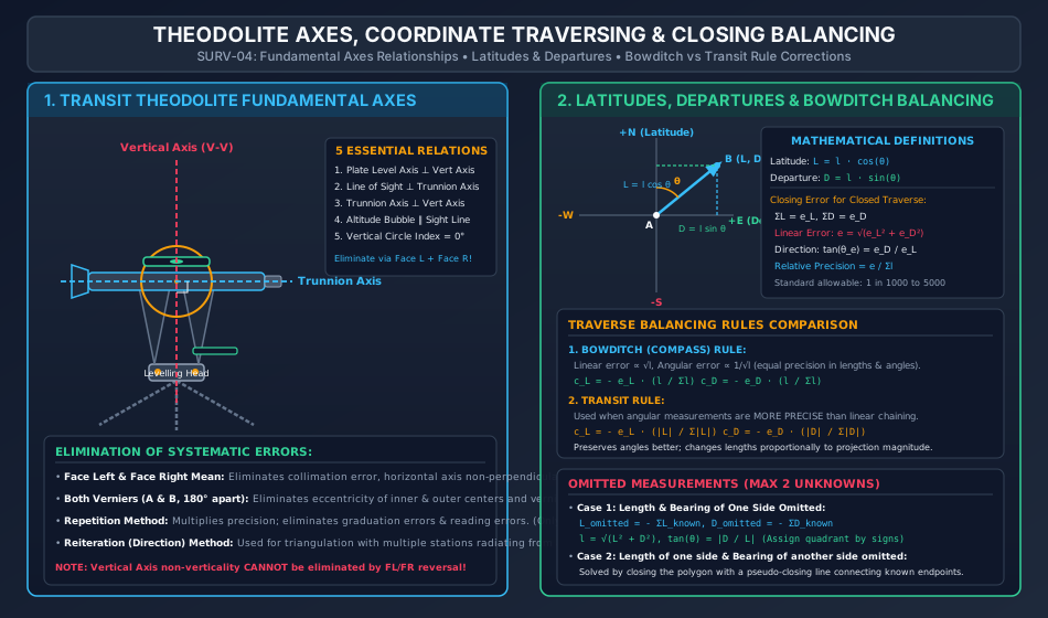
  1. Vertical Axis (V−VV-V): The axis about which the instrument rotates in the horizontal plane (axis of the inner and outer centers).
  2. Horizontal Axis / Trunnion Axis (H−HH-H): The axis about which the telescope rotates in the vertical plane.
  3. Line of Collimation (Line of Sight): The imaginary line passing through the optical center of the objective lens and the intersection of the cross-hairs of the reticle.
  4. Axis of the Plate Level: The straight line tangential to the internal longitudinal curve of the plate bubble tube at its center point.
  5. Axis of the Altitude Bubble Tube: The line tangential to the longitudinal curvature of the telescope or index level tube at its center.

3.2 Five Desired Geometric Relationships

In an ideally adjusted theodolite:

  1. Plate Level Axis ⊥\perp Vertical Axis: Ensures the horizontal plate is truly horizontal when the plate bubble is centered.
  2. Line of Sight ⊥\perp Horizontal (Trunnion) Axis: Ensures the line of collimation traces a true plane (not a cone) when plunged.
  3. Horizontal (Trunnion) Axis ⊥\perp Vertical Axis: Ensures the line of collimation rotates in a truly vertical plane.
  4. Altitude Bubble Axis ∥\parallel Line of Sight: Ensures true zero vertical datum when the telescope is horizontal.
  5. Vertical Circle Vernier reads 0∘00′00′′0^\circ 00' 00'' when line of sight is horizontal.

4. Systematic Instrumental Errors & Reversal Elimination Protocols

Instrumental Imperfection Nature of Error Produced Method of Complete Elimination Can it be eliminated by Face Left / Face Right?
Line of Collimation not ⊥\perp Trunnion Axis Produces horizontal angular displacement β=c⋅sec⁡α\beta = c \cdot \sec \alpha (where α\alpha is elevation angle). Take mean of Face Left (Circle Left) and Face Right (Circle Right) observations. YES
Trunnion Axis not ⊥\perp Vertical Axis Produces horizontal pointing error i=b⋅tan⁡αi = b \cdot \tan \alpha. Significant on steep sights. Take mean of Face Left and Face Right observations. YES
Vertical Circle Index Error Systematic offset on vertical angles (αobs=αtrue±ϵ\alpha_{\text{obs}} = \alpha_{\text{true}} \pm \epsilon). Take mean of Face Left and Face Right vertical angles: α=αL+αR2\alpha = \frac{\alpha_L + \alpha_R}{2}. YES
Eccentricity of Inner & Outer Centers Reading offset variable across graduated circle. Read both Verniers (A and B) positioned 180∘180^\circ apart and average them. YES (via Dual Verniers)
Eccentricity of Verniers Zero of verniers not exactly 180∘180^\circ opposite. Read both Verniers (A and B) and take mean. YES (via Dual Verniers)
Non-Verticality of Vertical Axis Causes trunnion axis and line of sight to trace oblique paths; error varies dynamically with azimuthal direction. CANNOT BE ELIMINATED BY FACE REVERSAL! Must be corrected strictly by careful levelling using plate foot screws. NO (Fatal Error!)

4.1 Horizontal Angle Measurement Techniques

  • Repetition Method: Angle measured multiple times (nn times) consecutively along the circle without resetting. Final reading divided by nn. θ=Final Reading+m⋅360∘−Initial Readingn\theta = \frac{\text{Final Reading} + m \cdot 360^\circ - \text{Initial Reading}}{n} Eliminates graduation errors and reading errors; applicable ONLY to horizontal angles.
  • Reiteration (Direction) Method: Several angles measured from a single central instrument station to multiple surrounding stations by sighting in sequence and "closing the horizon" back to the reference station. Preferred in primary triangulation.

5. Coordinate Traversing: Latitudes, Departures & Independent Coordinates

A traverse consists of a connected sequence of survey lines whose lengths are measured linearly (chain/tape/EDM) and whose relative directions are measured angularly (theodolite/compass).

5.1 Latitudes and Departures

For a traverse line ABAB having length ll and Whole Circle Bearing θ\theta:

  • Latitude (LL): Orthographic projection on the reference North-South meridian. L=lcos⁡θL = l \cos \theta
    • If pointing North (0∘≤θ<90∘0^\circ \le \theta < 90^\circ or 270∘<θ≤360∘270^\circ < \theta \le 360^\circ): Latitude is Positive (Northing).
    • If pointing South (90∘<θ<270∘90^\circ < \theta < 270^\circ): Latitude is Negative (Southing).
  • Departure (DD): Orthographic projection on the reference East-West line. D=lsin⁡θD = l \sin \theta
    • If pointing East (0∘<θ<180∘0^\circ < \theta < 180^\circ): Departure is Positive (Easting).
    • If pointing West (180∘<θ<360∘180^\circ < \theta < 360^\circ): Departure is Negative (Westing).
       Quadrant I (NE)  :  L = + l cos θ,  D = + l sin θ
       Quadrant II (SE) :  L = - l cos θ,  D = + l sin θ
       Quadrant III (SW):  L = - l cos θ,  D = - l sin θ
       Quadrant IV (NW) :  L = + l cos θ,  D = - l sin θ

5.2 Closing Error of a Closed Traverse

In a mathematically perfect closed loop traverse returning to its origin:

∑L=0and∑D=0\sum L = 0 \quad \text{and} \quad \sum D = 0

Due to random observational errors, practical surveys yield non-zero closures:

∑L=eL(Error in Latitude),∑D=eD(Error in Departure)\sum L = e_L \quad (\text{Error in Latitude}), \qquad \sum D = e_D \quad (\text{Error in Departure})
  1. Magnitude of Total Linear Closing Error (ee): e=eL2+eD2e = \sqrt{e_L^2 + e_D^2}
  2. Direction (Bearing) of Closing Error (θe\theta_e): tan⁡θe=eDeL  ⟹  θe=arctan⁡(∣eD∣∣eL∣)\tan \theta_e = \frac{e_D}{e_L} \implies \theta_e = \arctan\left(\frac{|e_D|}{|e_L|}\right) (Assigned to proper quadrant based on signs of eLe_L and eDe_D).
  3. Relative Precision (Degree of Accuracy): Relative Precision=e∑l=1(∑le)\text{Relative Precision} = \frac{e}{\sum l} = \frac{1}{\left(\frac{\sum l}{e}\right)} (Expressed as 1 in N1 \text{ in } N; standard cadastral requires 1:10001:1000 to 1:30001:3000, geodetic control >1:10000> 1:10000).

6. Traverse Balancing Mathematical Rules

When the closing error falls within permissible tolerances, it must be distributed across the traverse lines to close the mathematical polygon.

+---------------------------------------------------------------------------------------------------+
| METHOD              | CORRECTION TO LATITUDE (c_L)           | CORRECTION TO DEPARTURE (c_D)          |
+---------------------+----------------------------------------+----------------------------------------+
| Bowditch's Rule     | c_L = - e_L * ( l / \Sigma l )         | c_D = - e_D * ( l / \Sigma l )         |
| (Compass Rule)      |                                        |                                        |
+---------------------+----------------------------------------+----------------------------------------+
| Transit Rule        | c_L = - e_L * ( |L| / \Sigma |L| )     | c_D = - e_D * ( |D| / \Sigma |D| )     |
+---------------------+----------------------------------------+----------------------------------------+
| Axis Rule           | Line lengths held fixed; corrections applied purely to line directions.         |
+---------------------+----------------------------------------+----------------------------------------+

6.1 Bowditch's (Compass) Rule

  • Foundational Assumptions:
    1. Linear measurements are made with chain/tape where errors are accidental: Elinear∝lE_{\text{linear}} \propto \sqrt{l}.
    2. Angular measurements are made with compass/theodolite where errors are accidental: Eangular∝1lE_{\text{angular}} \propto \frac{1}{\sqrt{l}}.
    3. Total error distribution weights lengths and angles equally.
  • Mathematical Formulas: cL,i=−eL⋅li∑l,cD,i=−eD⋅li∑lc_{L, i} = - e_L \cdot \frac{l_i}{\sum l}, \qquad c_{D, i} = - e_D \cdot \frac{l_i}{\sum l} Corrected Li=Li+cL,i,Corrected Di=Di+cD,i\text{Corrected } L_i = L_i + c_{L, i}, \qquad \text{Corrected } D_i = D_i + c_{D, i}

6.2 The Transit Rule

  • Foundational Assumption:
    1. Angular measurements are significantly more precise than linear chaining (typical with modern theodolites).
    2. Corrections are applied proportionally to the magnitude of the coordinate components, thereby minimizing changes to measured angles.
  • Mathematical Formulas: cL,i=−eL⋅∣Li∣∑∣L∣,cD,i=−eD⋅∣Di∣∑∣D∣c_{L, i} = - e_L \cdot \frac{|L_i|}{\sum |L|}, \qquad c_{D, i} = - e_D \cdot \frac{|D_i|}{\sum |D|}

7. Omitted Measurements & Traverse Geometry Resolution

When physical obstructions (rivers, dense structures, steep ravines) prevent direct measurement of a line, missing values are deduced mathematically because a closed polygon provides two independent scalar equilibrium equations:

∑L=0  ⟹  ∑Lknown+Lunknown=0\sum L = 0 \implies \sum L_{\text{known}} + L_{\text{unknown}} = 0 ∑D=0  ⟹  ∑Dknown+Dunknown=0\sum D = 0 \implies \sum D_{\text{known}} + D_{\text{unknown}} = 0

7.1 Case 1: Length and Bearing of One Side Missing (Line kk)

This is the most common field case:

Lk=−∑i≠kLi,Dk=−∑i≠kDiL_k = - \sum_{i \ne k} L_i, \qquad D_k = - \sum_{i \ne k} D_i
  1. Length of Omitted Side (lkl_k): lk=Lk2+Dk2l_k = \sqrt{L_k^2 + D_k^2}
  2. Reduced Bearing (θk\theta_k): tan⁡θk=∣DkLk∣\tan \theta_k = \left|\frac{D_k}{L_k}\right|
    • Lk>0,Dk>0  ⟹  N θk E (WCB =θk)L_k > 0, D_k > 0 \implies \text{N } \theta_k \text{ E (WCB } = \theta_k)
    • Lk<0,Dk>0  ⟹  S θk E (WCB =180∘−θk)L_k < 0, D_k > 0 \implies \text{S } \theta_k \text{ E (WCB } = 180^\circ - \theta_k)
    • Lk<0,Dk<0  ⟹  S θk W (WCB =180∘+θk)L_k < 0, D_k < 0 \implies \text{S } \theta_k \text{ W (WCB } = 180^\circ + \theta_k)
    • Lk>0,Dk<0  ⟹  N θk W (WCB =360∘−θk)L_k > 0, D_k < 0 \implies \text{N } \theta_k \text{ W (WCB } = 360^\circ - \theta_k)

7.2 Case 2: Length of One Side and Bearing of Another Side Missing

Let line 11 have unknown length l1l_1 and known bearing θ1\theta_1. Let line 22 have known length l2l_2 and unknown bearing θ2\theta_2.

  1. Combine all known sides into a single closing line CC: LC=−∑knownL,DC=−∑knownDL_C = - \sum_{\text{known}} L, \qquad D_C = - \sum_{\text{known}} D
  2. The remaining triangle formed by l1,l2l_1, l_2, and CC has three known side lengths (or two sides and one known direction).
  3. Solve using trigonometry (Sine rule or Cosine rule). Note: May yield two mathematical solutions (ambiguity), resolved by field inspection.

8. Horizontal Circular Curves: Elements, Formulas & Chainage Relationships

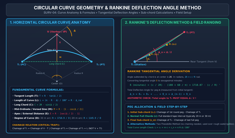
Horizontal curves provide gradual transition between intersecting tangent alignments, eliminating abrupt directional changes for vehicular transport.

Circular Curve Geometry & Rankine Deflection Method

8.1 Nomenclature and Anatomy

  • Intersection Point (Vertex / Apex, VV): Point where initial tangent and forward tangent intersect.
  • Deflection Angle (Δ\Delta): Angle through which the alignment deflects at VV.
  • Intersection Angle (II): Internal angle between tangents (I=180∘−ΔI = 180^\circ - \Delta).
  • Point of Curve (PC or T1T_1): Point where curve commences from the rear tangent.
  • Point of Tangency (PT or T2T_2): Point where curve terminates into the forward tangent.
  • Radius (RR): Radius of the circular arc.

8.2 Standard Curve Formulas

  1. Tangent Length (TT): T=VT1=VT2=Rtan⁡(Δ2)T = V T_1 = V T_2 = R \tan\left(\frac{\Delta}{2}\right)
  2. Length of Curve (LL): L=Arc T1CT2=πRΔ180∘=R⋅ΔradL = \text{Arc } T_1 C T_2 = \frac{\pi R \Delta}{180^\circ} = R \cdot \Delta_{\text{rad}}
  3. Length of Long Chord (CC): C=2Rsin⁡(Δ2)C = 2 R \sin\left(\frac{\Delta}{2}\right)
  4. Mid-Ordinate / Versed Sine (MM): M=R−Rcos⁡(Δ2)=R[1−cos⁡(Δ2)]M = R - R \cos\left(\frac{\Delta}{2}\right) = R \left[1 - \cos\left(\frac{\Delta}{2}\right)\right]
  5. Apex Distance / External Distance (EE): E=VC=R[sec⁡(Δ2)−1]E = V C = R \left[\sec\left(\frac{\Delta}{2}\right) - 1\right]
  6. Degree of Curve (DD):
    • For 30 m Arc Definition: R=30×180∘πD≈1718.87D≈1719D mR = \frac{30 \times 180^\circ}{\pi D} \approx \frac{1718.87}{D} \approx \frac{1719}{D} \text{ m}
    • For 20 m Arc Definition: R=20×180∘πD≈1145.92D≈1146D mR = \frac{20 \times 180^\circ}{\pi D} \approx \frac{1145.92}{D} \approx \frac{1146}{D} \text{ m}

8.3 Chainage Calculation Sequence (Critical Rule)

Curve chainage follows the actual path of travel along the curve arc:

Chainage of PC (T1)=Chainage of Vertex (V)−T\text{Chainage of PC } (T_1) = \text{Chainage of Vertex } (V) - T Chainage of PT (T2)=Chainage of PC (T1)+L\text{Chainage of PT } (T_2) = \text{Chainage of PC } (T_1) + L Chainage of T2≠Chainage of V+T(Common Trapping Error!)\mathbf{\text{Chainage of } T_2 \ne \text{Chainage of } V + T} \quad (\text{Common Trapping Error!})

9. Linear & Angular Methods of Curve Ranging

9.1 Linear Methods (Chain and Tape Only)

Used when high optical precision is not required or instruments are unavailable:

  1. Offsets from Long Chord: Ox=R2−x2−(R−M)≈M−x22RO_x = \sqrt{R^2 - x^2} - (R - M) \approx M - \frac{x^2}{2R} (where xx is distance measured from midpoint of long chord).
  2. Offsets from Tangents:
    • Radial offsets: Ox=R2+x2−R≈x22RO_x = \sqrt{R^2 + x^2} - R \approx \frac{x^2}{2R}
    • Perpendicular offsets: Ox=R−R2−x2≈x22RO_x = R - \sqrt{R^2 - x^2} \approx \frac{x^2}{2R}
  3. Offsets from Chords Produced:
    • First chord offset: O1=c122RO_1 = \frac{c_1^2}{2R}
    • Intermediate chords: Oi=c(c+ci−1)2RO_i = \frac{c (c + c_{i-1})}{2R}; for equal chords cc: O=c2RO = \frac{c^2}{R}
    • Last chord offset: On=cn(c+cn)2RO_n = \frac{c_n (c + c_n)}{2R}

9.2 Angular Methods (Theodolite Based)

  1. Rankine's Tangential Deflection Angle Method: Single theodolite at T1T_1, tape for chord measurements. Standard highway/railway technique.
  2. Two-Theodolite Method: Instruments placed at both T1T_1 and T2T_2. No linear taping needed; points located by optical intersection of simultaneous sightlines (Δi\Delta_i from T1T_1 and Δ−Δi\Delta - \Delta_i from T2T_2). Ideal for steep ravines, swift rivers, and rough ground.

10. Rankine's Method of Tangential Angles & Detailed Deflection Computations

10.1 Mathematical Derivation

Let P1,P2,…,PnP_1, P_2, \dots, P_n be points pegged on the curve arc at chord lengths c1,c2,…,cnc_1, c_2, \dots, c_n. The angle subtended by chord cic_i at the center of the curve is 2δi2 \delta_i. By the geometric property of a circle, the tangential angle δi\delta_i between the tangent at the chord start and the chord itself is half the central angle:

Central angle=2δi=ciR radians  ⟹  δi=ci2R radians\text{Central angle} = 2 \delta_i = \frac{c_i}{R} \text{ radians} \implies \delta_i = \frac{c_i}{2R} \text{ radians}

Converting radians to sexagesimal minutes:

δi=ci2R×180∘×60′π=ci2R×10800′π=5400π⋅ciR=1718.873⋅ciR minutes\delta_i = \frac{c_i}{2R} \times \frac{180^\circ \times 60'}{\pi} = \frac{c_i}{2R} \times \frac{10800'}{\pi} = \frac{5400}{\pi} \cdot \frac{c_i}{R} = 1718.873 \cdot \frac{c_i}{R} \text{ minutes} δi(minutes)=1718.87×ciR(ci,R in meters)\mathbf{\delta_i (\text{minutes}) = 1718.87 \times \frac{c_i}{R}} \quad (c_i, R \text{ in meters})

10.2 Total Deflection Angles (Δi\Delta_i)

The total deflection angle Δi\Delta_i measured from the initial tangent VT1V T_1 to station PiP_i is the cumulative sum of all preceding tangential angles:

Δ1=δ1\Delta_1 = \delta_1 Δ2=δ1+δ2=Δ1+δ2\Delta_2 = \delta_1 + \delta_2 = \Delta_1 + \delta_2 Δ3=Δ2+δ3\Delta_3 = \Delta_2 + \delta_3 Δn=Δn−1+δn\Delta_n = \Delta_{n-1} + \delta_n

10.3 Golden Verification Check

The total deflection angle to the final point of tangency T2T_2 must exactly equal half the total deflection angle of the curve:

Δn=Δ2\mathbf{\Delta_n = \frac{\Delta}{2}}

10.4 Peg Interval and Sub-chords

Chainages of pegs must fall on regular round numbers (multiples of 20 m20\text{ m} or 30 m30\text{ m}):

  • Initial Sub-chord (c1c_1): Brings the chainage from T1T_1 to the very first rounded station: c1=Chainage of first full station−Chainage of T1c_1 = \text{Chainage of first full station} - \text{Chainage of } T_1
  • Normal Chords (cc): Standard peg intervals (20 m20\text{ m} or 30 m30\text{ m}).
  • Final Sub-chord (cnc_n): Brings the chainage from the last full station to T2T_2: cn=Chainage of T2−Chainage of last full stationc_n = \text{Chainage of } T_2 - \text{Chainage of last full station}

11. Step-by-Step Rigorous Worked Numerical Examples

Problem 1: Closed Traverse Balancing by Bowditch's Rule

Problem Statement:
The coordinates of a 4-sided closed traverse ABCDABCD were surveyed as follows:

  • Line ABAB: Length l=100.00 ml = 100.00\text{ m}, Whole Circle Bearing θ=30∘00′\theta = 30^\circ 00'
  • Line BCBC: Length l=150.00 ml = 150.00\text{ m}, Whole Circle Bearing θ=110∘00′\theta = 110^\circ 00'
  • Line CDCD: Length l=120.00 ml = 120.00\text{ m}, Whole Circle Bearing θ=210∘00′\theta = 210^\circ 00'
  • Line DADA: Length l=148.00 ml = 148.00\text{ m}, Whole Circle Bearing θ=297∘30′\theta = 297^\circ 30'

Compute:

  1. The total Latitude and Departure closures (eL,eDe_L, e_D).
  2. Total linear closing error (ee), its direction (θe\theta_e), and the relative precision.
  3. Bowditch corrections and the final balanced Latitudes and Departures.

Step 1: Compute Raw Latitudes and Departures

  • Line ABAB: LAB=100.00×cos⁡30∘=+86.603 mL_{AB} = 100.00 \times \cos 30^\circ = +86.603\text{ m} DAB=100.00×sin⁡30∘=+50.000 mD_{AB} = 100.00 \times \sin 30^\circ = +50.000\text{ m}
  • Line BCBC: LBC=150.00×cos⁡110∘=150.00×(−0.34202)=−51.303 mL_{BC} = 150.00 \times \cos 110^\circ = 150.00 \times (-0.34202) = -51.303\text{ m} DBC=150.00×sin⁡110∘=150.00×(+0.93969)=+140.954 mD_{BC} = 150.00 \times \sin 110^\circ = 150.00 \times (+0.93969) = +140.954\text{ m}
  • Line CDCD: LCD=120.00×cos⁡210∘=120.00×(−0.86603)=−103.923 mL_{CD} = 120.00 \times \cos 210^\circ = 120.00 \times (-0.86603) = -103.923\text{ m} DCD=120.00×sin⁡210∘=120.00×(−0.50000)=−60.000 mD_{CD} = 120.00 \times \sin 210^\circ = 120.00 \times (-0.50000) = -60.000\text{ m}
  • Line DADA: LDA=148.00×cos⁡297∘30′=148.00×(+0.46175)=+68.339 mL_{DA} = 148.00 \times \cos 297^\circ 30' = 148.00 \times (+0.46175) = +68.339\text{ m} DDA=148.00×sin⁡297∘30′=148.00×(−0.88701)=−131.278 mD_{DA} = 148.00 \times \sin 297^\circ 30' = 148.00 \times (-0.88701) = -131.278\text{ m}

Step 2: Summation and Closures

∑l=100.00+150.00+120.00+148.00=518.00 m\sum l = 100.00 + 150.00 + 120.00 + 148.00 = 518.00\text{ m} ∑L=+86.603−51.303−103.923+68.339=−0.285 m  ⟹  eL=−0.285 m\sum L = +86.603 - 51.303 - 103.923 + 68.339 = -0.285\text{ m} \implies e_L = -0.285\text{ m} ∑D=+50.000+140.954−60.000−131.278=−0.324 m  ⟹  eD=−0.324 m\sum D = +50.000 + 140.954 - 60.000 - 131.278 = -0.324\text{ m} \implies e_D = -0.324\text{ m}

Step 3: Total Closing Error and Precision

e=eL2+eD2=(−0.285)2+(−0.324)2=0.081225+0.104976=0.186201=0.4315 m≈0.432 me = \sqrt{e_L^2 + e_D^2} = \sqrt{(-0.285)^2 + (-0.324)^2} = \sqrt{0.081225 + 0.104976} = \sqrt{0.186201} = 0.4315\text{ m} \approx 0.432\text{ m} tan⁡θe=eDeL=−0.324−0.285=+1.1368  ⟹  θref=48∘40′\tan \theta_e = \frac{e_D}{e_L} = \frac{-0.324}{-0.285} = +1.1368 \implies \theta_{\text{ref}} = 48^\circ 40'

Since both eLe_L and eDe_D are negative, the closing vector lies in Quadrant III:

WCB of error=180∘+48∘40′=228∘40′\text{WCB of error} = 180^\circ + 48^\circ 40' = 228^\circ 40' Relative Precision=e∑l=0.4315518.00=11200.5≈11200\text{Relative Precision} = \frac{e}{\sum l} = \frac{0.4315}{518.00} = \frac{1}{1200.5} \approx \frac{1}{1200}

Step 4: Bowditch Balancing Corrections

cL,i=−(−0.285)×li518.00=+0.285×li518.00c_{L, i} = - (-0.285) \times \frac{l_i}{518.00} = +0.285 \times \frac{l_i}{518.00} cD,i=−(−0.324)×li518.00=+0.324×li518.00c_{D, i} = - (-0.324) \times \frac{l_i}{518.00} = +0.324 \times \frac{l_i}{518.00}
  • Line ABAB (l=100 ml = 100\text{ m}): cL=+0.285×100518=+0.055 m  ⟹  Lcorr=+86.603+0.055=+86.658 mc_L = +0.285 \times \frac{100}{518} = +0.055\text{ m} \implies L_{\text{corr}} = +86.603 + 0.055 = +86.658\text{ m} cD=+0.324×100518=+0.062 m  ⟹  Dcorr=+50.000+0.062=+50.062 mc_D = +0.324 \times \frac{100}{518} = +0.062\text{ m} \implies D_{\text{corr}} = +50.000 + 0.062 = +50.062\text{ m}
  • Line BCBC (l=150 ml = 150\text{ m}): cL=+0.285×150518=+0.083 m  ⟹  Lcorr=−51.303+0.083=−51.220 mc_L = +0.285 \times \frac{150}{518} = +0.083\text{ m} \implies L_{\text{corr}} = -51.303 + 0.083 = -51.220\text{ m} cD=+0.324×150518=+0.094 m  ⟹  Dcorr=+140.954+0.094=+141.048 mc_D = +0.324 \times \frac{150}{518} = +0.094\text{ m} \implies D_{\text{corr}} = +140.954 + 0.094 = +141.048\text{ m}
  • Line CDCD (l=120 ml = 120\text{ m}): cL=+0.285×120518=+0.066 m  ⟹  Lcorr=−103.923+0.066=−103.857 mc_L = +0.285 \times \frac{120}{518} = +0.066\text{ m} \implies L_{\text{corr}} = -103.923 + 0.066 = -103.857\text{ m} cD=+0.324×120518=+0.075 m  ⟹  Dcorr=−60.000+0.075=−59.925 mc_D = +0.324 \times \frac{120}{518} = +0.075\text{ m} \implies D_{\text{corr}} = -60.000 + 0.075 = -59.925\text{ m}
  • Line DADA (l=148 ml = 148\text{ m}): cL=+0.285×148518=+0.081 m  ⟹  Lcorr=+68.339+0.081=+68.420 mc_L = +0.285 \times \frac{148}{518} = +0.081\text{ m} \implies L_{\text{corr}} = +68.339 + 0.081 = +68.420\text{ m} cD=+0.324×148518=+0.093 m  ⟹  Dcorr=−131.278+0.093=−131.185 mc_D = +0.324 \times \frac{148}{518} = +0.093\text{ m} \implies D_{\text{corr}} = -131.278 + 0.093 = -131.185\text{ m}

Final Check:

∑Lcorr=+86.658−51.220−103.857+68.420=0.001≈0.000 m\sum L_{\text{corr}} = +86.658 - 51.220 - 103.857 + 68.420 = 0.001 \approx 0.000\text{ m} ∑Dcorr=+50.062+141.048−59.925−131.185=0.000 m[Balanced!]\sum D_{\text{corr}} = +50.062 + 141.048 - 59.925 - 131.185 = 0.000\text{ m} \quad \text{[Balanced!]}

Problem 2: Resolution of Omitted Traverse Measurements

Problem Statement:
In the 4-sided closed traverse ABCDABCD, boundary obstructions prevented the measurement of both the length and bearing of line DADA. The remaining survey measurements are:

  • Line ABAB: l=100.00 ml = 100.00\text{ m}, Bearing =30∘00′= 30^\circ 00'
  • Line BCBC: l=150.00 ml = 150.00\text{ m}, Bearing =110∘00′= 110^\circ 00'
  • Line CDCD: l=120.00 ml = 120.00\text{ m}, Bearing =210∘00′= 210^\circ 00'

Determine the length and whole circle bearing of line DADA.

Step 1: Compute Latitudes and Departures of Known Lines

From Problem 1:

  • Line ABAB: L=+86.603 mL = +86.603\text{ m}, D=+50.000 mD = +50.000\text{ m}
  • Line BCBC: L=−51.303 mL = -51.303\text{ m}, D=+140.954 mD = +140.954\text{ m}
  • Line CDCD: L=−103.923 mL = -103.923\text{ m}, D=−60.000 mD = -60.000\text{ m}

Step 2: Sum Known Coordinates

∑Lknown=+86.603−51.303−103.923=−68.623 m\sum L_{\text{known}} = +86.603 - 51.303 - 103.923 = -68.623\text{ m} ∑Dknown=+50.000+140.954−60.000=+130.954 m\sum D_{\text{known}} = +50.000 + 140.954 - 60.000 = +130.954\text{ m}

Step 3: Apply Equilibrium Conditions for Line DADA

∑L=0  ⟹  ∑Lknown+LDA=0  ⟹  LDA=−∑Lknown=−(−68.623)=+68.623 m\sum L = 0 \implies \sum L_{\text{known}} + L_{DA} = 0 \implies L_{DA} = - \sum L_{\text{known}} = -(-68.623) = +68.623\text{ m} ∑D=0  ⟹  ∑Dknown+DDA=0  ⟹  DDA=−∑Dknown=−(+130.954)=−130.954 m\sum D = 0 \implies \sum D_{\text{known}} + D_{DA} = 0 \implies D_{DA} = - \sum D_{\text{known}} = -(+130.954) = -130.954\text{ m}

Step 4: Calculate Length and Bearing of Line DADA

lDA=LDA2+DDA2=(68.623)2+(−130.954)2=4709.116+17148.950=21858.066=147.845 m≈147.85 ml_{DA} = \sqrt{L_{DA}^2 + D_{DA}^2} = \sqrt{(68.623)^2 + (-130.954)^2} = \sqrt{4709.116 + 17148.950} = \sqrt{21858.066} = 147.845\text{ m} \approx 147.85\text{ m} tan⁡θ=∣DDALDA∣=130.95468.623=1.90831  ⟹  θ=62.3444∘=62∘20′40′′\tan \theta = \left|\frac{D_{DA}}{L_{DA}}\right| = \frac{130.954}{68.623} = 1.90831 \implies \theta = 62.3444^\circ = 62^\circ 20' 40''

Since LDAL_{DA} is positive (++, North) and DDAD_{DA} is negative (−-, West), the line lies in Quadrant IV (North-West):

Quadrant Bearing=N 62∘20′40′′ W\text{Quadrant Bearing} = \text{N } 62^\circ 20' 40'' \text{ W} WCB=360∘−62∘20′40′′=297∘39′20′′\text{WCB} = 360^\circ - 62^\circ 20' 40'' = 297^\circ 39' 20''

Problem 3: Setting Out a Circular Curve by Rankine's Method

Problem Statement:
Two straights intersect at chainage 2450.00 m2450.00\text{ m} with a deflection angle Δ=48∘00′\Delta = 48^\circ 00'. A simple circular curve of radius R=300.00 mR = 300.00\text{ m} is to be set out using a transit theodolite and standard peg interval of 20.00 m20.00\text{ m}. Calculate:

  1. Tangent length, curve length, and chainages of PC (T1T_1) and PT (T2T_2).
  2. Length of the initial sub-chord, number of standard chords, and length of the final sub-chord.
  3. Individual tangential angles (δi\delta_i) and total deflection angles (Δi\Delta_i) for setting out all pegs.

Step 1: Curve Parameters

  1. Tangent Length (TT): T=Rtan⁡(Δ2)=300.00×tan⁡(24∘)=300.00×0.445229=133.569 mT = R \tan\left(\frac{\Delta}{2}\right) = 300.00 \times \tan(24^\circ) = 300.00 \times 0.445229 = 133.569\text{ m}
  2. Length of Curve (LL): L=πRΔ180∘=π×300.00×48∘180∘=80π=251.327 mL = \frac{\pi R \Delta}{180^\circ} = \frac{\pi \times 300.00 \times 48^\circ}{180^\circ} = 80 \pi = 251.327\text{ m}
  3. Chainages: Chainage of PC (T1)=Chainage of V−T=2450.00−133.569=2316.431 m\text{Chainage of PC } (T_1) = \text{Chainage of } V - T = 2450.00 - 133.569 = 2316.431\text{ m} Chainage of PT (T2)=Chainage of T1+L=2316.431+251.327=2567.758 m\text{Chainage of PT } (T_2) = \text{Chainage of } T_1 + L = 2316.431 + 251.327 = 2567.758\text{ m}

Step 2: Chord Allocation

  • The standard peg interval is 20.00 m20.00\text{ m}.
  • Chainage of T1=2316.431 mT_1 = 2316.431\text{ m}. The first whole peg on the curve is at chainage 2320.00 m2320.00\text{ m}. c1=2320.00−2316.431=3.569 m(Initial sub-chord)c_1 = 2320.00 - 2316.431 = 3.569\text{ m} \quad (\text{Initial sub-chord})
  • Full pegs run from 2320.00 m2320.00\text{ m} up to 2560.00 m2560.00\text{ m}: nfull=2560.00−2320.0020.00=12 full chords of 20.00 mn_{\text{full}} = \frac{2560.00 - 2320.00}{20.00} = 12 \text{ full chords of } 20.00\text{ m}
  • Chainage of last full peg =2560.00 m= 2560.00\text{ m}. Chainage of T2=2567.758 mT_2 = 2567.758\text{ m}: cn=2567.758−2560.00=7.758 m(Final sub-chord)c_n = 2567.758 - 2560.00 = 7.758\text{ m} \quad (\text{Final sub-chord})
  • Verification of total chord lengths: ∑c=3.569+(12×20.00)+7.758=3.569+240.00+7.758=251.327 m=L[Exact!]\sum c = 3.569 + (12 \times 20.00) + 7.758 = 3.569 + 240.00 + 7.758 = 251.327\text{ m} = L \quad \text{[Exact!]}

Step 3: Computation of Tangential Angles (δi\delta_i)

Formula: δi=1718.87×ciR minutes\delta_i = 1718.87 \times \frac{c_i}{R} \text{ minutes} (with R=300 mR = 300\text{ m}):

  • For Initial Sub-chord (c1=3.569 mc_1 = 3.569\text{ m}): δ1=1718.87×3.569300=20.450′=20′27′′\delta_1 = 1718.87 \times \frac{3.569}{300} = 20.450' = 20' 27''
  • For Each Normal Full Chord (c=20.00 mc = 20.00\text{ m}): δfull=1718.87×20.00300=114.591′=1∘54′35.5′′\delta_{\text{full}} = 1718.87 \times \frac{20.00}{300} = 114.591' = 1^\circ 54' 35.5''
  • For Final Sub-chord (cn=7.758 mc_n = 7.758\text{ m}): δn=1718.87×7.758300=44.453′=44′27′′\delta_n = 1718.87 \times \frac{7.758}{300} = 44.453' = 44' 27''

Step 4: Total Cumulative Deflection Angles Table

Peg No. Chainage (m) Chord Length cic_i (m) Tangential Angle δi\delta_i Total Deflection Angle Δi=Δi−1+δi\Delta_i = \Delta_{i-1} + \delta_i Theodolite Vernier Setting
T1T_1 2316.4312316.431 — — 0∘00′00′′0^\circ 00' 00'' 0∘00′00′′0^\circ 00' 00''
11 2320.002320.00 3.5693.569 0∘20′27′′0^\circ 20' 27'' 0∘20′27′′0^\circ 20' 27'' 0∘20′30′′0^\circ 20' 30''
22 2340.002340.00 20.00020.000 1∘54′36′′1^\circ 54' 36'' 2∘15′03′′2^\circ 15' 03'' 2∘15′00′′2^\circ 15' 00''
33 2360.002360.00 20.00020.000 1∘54′36′′1^\circ 54' 36'' 4∘09′39′′4^\circ 09' 39'' 4∘09′40′′4^\circ 09' 40''
44 2380.002380.00 20.00020.000 1∘54′36′′1^\circ 54' 36'' 6∘04′15′′6^\circ 04' 15'' 6∘04′20′′6^\circ 04' 20''
55 2400.002400.00 20.00020.000 1∘54′36′′1^\circ 54' 36'' 7∘58′51′′7^\circ 58' 51'' 7∘59′00′′7^\circ 59' 00''
66 2420.002420.00 20.00020.000 1∘54′36′′1^\circ 54' 36'' 9∘53′27′′9^\circ 53' 27'' 9∘53′30′′9^\circ 53' 30''
77 2440.002440.00 20.00020.000 1∘54′36′′1^\circ 54' 36'' 11∘48′03′′11^\circ 48' 03'' 11∘48′00′′11^\circ 48' 00''
88 2460.002460.00 20.00020.000 1∘54′36′′1^\circ 54' 36'' 13∘42′39′′13^\circ 42' 39'' 13∘42′40′′13^\circ 42' 40''
99 2480.002480.00 20.00020.000 1∘54′36′′1^\circ 54' 36'' 15∘37′15′′15^\circ 37' 15'' 15∘37′20′′15^\circ 37' 20''
1010 2500.002500.00 20.00020.000 1∘54′36′′1^\circ 54' 36'' 17∘31′51′′17^\circ 31' 51'' 17∘32′00′′17^\circ 32' 00''
1111 2520.002520.00 20.00020.000 1∘54′36′′1^\circ 54' 36'' 19∘26′27′′19^\circ 26' 27'' 19∘26′30′′19^\circ 26' 30''
1212 2540.002540.00 20.00020.000 1∘54′36′′1^\circ 54' 36'' 21∘21′03′′21^\circ 21' 03'' 21∘21′00′′21^\circ 21' 00''
1313 2560.002560.00 20.00020.000 1∘54′36′′1^\circ 54' 36'' 23∘15′39′′23^\circ 15' 39'' 23∘15′40′′23^\circ 15' 40''
T2T_2 2567.7582567.758 7.7587.758 0∘44′27′′0^\circ 44' 27'' 24∘00′06′′≈24∘00′00′′\mathbf{24^\circ 00' 06'' \approx 24^\circ 00' 00''} 24∘00′00′′24^\circ 00' 00''

Final Verification:

Δtotal=20.450′+(12×114.5913′)+44.453′=20.450′+1375.096′+44.453′=1440.00′=144060∘=24∘00′00′′\Delta_{\text{total}} = 20.450' + (12 \times 114.5913') + 44.453' = 20.450' + 1375.096' + 44.453' = 1440.00' = \frac{1440}{60}^\circ = \mathbf{24^\circ 00' 00''} Δ2=48∘00′2=24∘00′00′′[EXACT CHECK SATISFIED!]\frac{\Delta}{2} = \frac{48^\circ 00'}{2} = \mathbf{24^\circ 00' 00''} \quad \mathbf{\text{[EXACT CHECK SATISFIED!]}}

12. Comprehensive Exam Question Bank

Section A: GATE CE Previous Years & Anticipated Styles

  1. [GATE CE] In a closed traverse ABCDABCD, the sum of latitudes is −1.20 m-1.20\text{ m} and the sum of departures is +1.60 m+1.60\text{ m}. The perimeter of the traverse is 1000 m1000\text{ m}. If the length of line ABAB is 250 m250\text{ m}, the Bowditch correction to the latitude of line ABAB is:
    • (A) +0.30 m+0.30\text{ m}
    • (B) −0.30 m-0.30\text{ m}
    • (C) +0.40 m+0.40\text{ m}
    • (D) −0.40 m-0.40\text{ m}
      Answer: (A). cL=−eLl∑l=−(−1.20)×2501000=+0.30 mc_L = - e_L \frac{l}{\sum l} = -(-1.20) \times \frac{250}{1000} = +0.30\text{ m}.
  2. [GATE CE] A circular curve of radius 400 m400\text{ m} has a deflection angle of 60∘60^\circ. If the chainage of the intersection point is 1500.00 m1500.00\text{ m}, the chainage of the point of curvature (PC) in meters is:
    • (A) 1269.06 m1269.06\text{ m}
    • (B) 1230.94 m1230.94\text{ m}
    • (C) 1080.97 m1080.97\text{ m}
    • (D) 1730.94 m1730.94\text{ m}
      Answer: (A). T=Rtan⁡(Δ/2)=400×tan⁡30∘=400×0.57735=230.94 mT = R \tan(\Delta/2) = 400 \times \tan 30^\circ = 400 \times 0.57735 = 230.94\text{ m}. Chainage =1500.00−230.94=1269.06 m= 1500.00 - 230.94 = 1269.06\text{ m}.

Section B: UPSC ESE Conventional Practice

  1. [ESE Mains] Explain with mathematical diagrams why the Bowditch rule is preferred when linear measurements are made with a chain and angles with a compass, whereas the Transit rule is preferred when theodolite angular observations are of superior precision. State the equations for both and show how relative weights are assigned.

Section C: SSC JE & State AE/JE Quick Fire

  1. The method of measuring horizontal angles most suited for establishing control networks with multiple radiation lines from a single instrument hub is:
    • (A) Repetition method
    • (B) Reiteration method
    • (C) Deflection angle method
    • (D) Double observation method
      Answer: (B) Reiteration method.
  2. In Rankine's method of deflection angles, the tangential angle δ\delta in minutes for a chord cc and radius RR is given by:
    • (A) 1718.87Rc1718.87 \frac{R}{c}
    • (B) 1718.87cR1718.87 \frac{c}{R}
    • (C) 57.3cR57.3 \frac{c}{R}
    • (D) 1146cR1146 \frac{c}{R}
      Answer: (B).
  3. Which of the following instrumental errors CANNOT be eliminated by taking the mean of Face Left and Face Right theodolite observations?
    • (A) Horizontal collimation error
    • (B) Index error of vertical circle
    • (C) Non-perpendicularity of trunnion axis to vertical axis
    • (D) Non-verticality of the vertical axis
      Answer: (D).

13. Common Conceptual Pitfalls & Field Traps

  1. PT Chainage Addition Trap:
    Calculating chainage of PT (T2T_2) as Chainage of V+T\text{Chainage of } V + T.
    Field Reality: Vehicles travel along the curved arc T1T2T_1 T_2, not along the straight tangents through VV. Always compute: Chainage of T2=Chainage of T1+L\text{Chainage of } T_2 = \text{Chainage of } T_1 + L
  2. Bowditch Sign Convention Trap:
    Applying corrections with the same sign as the closing error.
    Field Reality: A negative closure (eL<0e_L < 0) indicates the polygon fell short; hence corrections must be positive (++) to expand the perimeter and close the gap: Correction=−(Error)\text{Correction} = - (\text{Error})
  3. Transit Rule Absolute Denominator Trap:
    Using algebraic sums ∑L\sum L in the denominator of the Transit rule rather than the sum of absolute values ∑∣L∣\sum |L|.
    Field Reality: Algebraic sum ∑L\sum L is simply the error eLe_L! The Transit rule denominator must be ∑∣L∣=∑(Northings)+∑(Southings)\sum |L| = \sum (\text{Northings}) + \sum (\text{Southings}).
  4. Rankine Tangential vs Central Angle Trap:
    Confusing the tangential deflection angle δ\delta with the central angle subtended by the chord (2δ2\delta). The tangential angle is strictly half the central angle!
  5. Level Bubble Sensitivity Trap:
    Assuming face reversal cures plate bubble unlevelness. If the vertical axis is tilted by ϵ\epsilon, it remains tilted by ϵ\epsilon after a 180∘180^\circ rotation; the error cannot be eliminated optically and corrupts all horizontal pointing.
14. Quick Reference Formulas & Multi-Code Summary Table

Category Parameter Exact Analytical Formulation
Traverse Coordinates Latitude (LL) L=lcos⁡θL = l \cos \theta (+North,−South+ \text{North}, - \text{South})
Departure (DD) D=lsin⁡θD = l \sin \theta (+East,−West+ \text{East}, - \text{West})
Traverse Closures Total Linear Error (ee) e=(∑L)2+(∑D)2e = \sqrt{(\sum L)^2 + (\sum D)^2}
Error Bearing (θe\theta_e) tan⁡θe=∑D∑L=eDeL\tan \theta_e = \frac{\sum D}{\sum L} = \frac{e_D}{e_L}
Relative Precision Precision=e∑l=1∑l/e\text{Precision} = \frac{e}{\sum l} = \frac{1}{\sum l / e}
Traverse Balancing Bowditch Latitude Correction cL,i=−eL⋅li∑lc_{L, i} = - e_L \cdot \frac{l_i}{\sum l}
Bowditch Departure Correction cD,i=−eD⋅li∑lc_{D, i} = - e_D \cdot \frac{l_i}{\sum l}
Transit Latitude Correction cL,i=−eL⋅∥Li∥∑∥L∥c_{L, i} = - e_L \cdot \frac{\|L_i\|}{\sum \|L\|}
Transit Departure Correction cD,i=−eD⋅∥Di∥∑∥D∥c_{D, i} = - e_D \cdot \frac{\|D_i\|}{\sum \|D\|}
Circular Curves Tangent Distance (TT) T=Rtan⁡(Δ/2)T = R \tan(\Delta / 2)
Curve Arc Length (LL) L=πRΔ180∘L = \frac{\pi R \Delta}{180^\circ}
Long Chord (CC) C=2Rsin⁡(Δ/2)C = 2 R \sin(\Delta / 2)
Mid-Ordinate / Versed Sine (MM) M=R[1−cos⁡(Δ/2)]M = R [1 - \cos(\Delta / 2)]
Apex External Distance (EE) E=R[sec⁡(Δ/2)−1]E = R [\sec(\Delta / 2) - 1]
Degree of Curve (D30D_{30}) R≈1718.87D mR \approx \frac{1718.87}{D} \text{ m} (for 30 m30\text{ m} arc)
Degree of Curve (D20D_{20}) R≈1145.92D mR \approx \frac{1145.92}{D} \text{ m} (for 20 m20\text{ m} arc)
Rankine Ranging Tangential Angle (δi\delta_i) δi=1718.87⋅ciR minutes\delta_i = 1718.87 \cdot \frac{c_i}{R} \text{ minutes}
Cumulative Deflection (Δi\Delta_i) Δi=Δi−1+δi\Delta_i = \Delta_{i-1} + \delta_i
Final Tangency Check Δn=Δ2\Delta_n = \frac{\Delta}{2}
Chainage Relations Point of Curve (T1T_1) Chainage of T1=Chainage of V−T\text{Chainage of } T_1 = \text{Chainage of } V - T
Point of Tangency (T2T_2) Chainage of T2=Chainage of T1+L\text{Chainage of } T_2 = \text{Chainage of } T_1 + L