Levelling & Contouring — Differential Levelling, Inverted Staff, Curvature & Refraction, Reciprocal Levelling, Bubble Tube Sensitivity, and Contour Volumetrics
In this chapter (1 topics)
On this page
- 1. Module Overview & Technical Architecture
- Functional Physics & Geometry of Levelling
- 2. Governing Formulae, Empirical Relations & Code Provisions
- 2.1 Methods of Level Reduction & Complete Arithmetic Checks
- 2.2 Curvature, Refraction & Combined Corrections
- 2.3 Distance to the Visible Sea Horizon (d)
- 2.4 Reciprocal Levelling Formulation
- 2.5 Sensitivity of the Bubble Tube
- 3. Step-by-Step Analytical Derivations & Mechanisms
- 3.1 Derivation of Earth Curvature Correction (Cc)
- 3.2 Atmospheric Refraction Mechanics (Cr)
- 3.3 Mathematical Proof of Error Elimination in Reciprocal Levelling
- 4. Field Levelling Operations: Setup, Backsight, Foresight & Inverted Staff
- 4.1 Step-by-Step Field Procedure
- 4.2 Inverted Staff Mechanics (Ceilings & Bridge Soffits)
- 5. Errors in Levelling: Collimation Error & Two-Peg Test Calibration
- 5.1 Collimation Error
- 5.2 The Two-Peg Test (Collimation Calibration Protocol)
- 6. Reciprocal Levelling: Precision Across Rivers & Ravines
- 7. Sensitivity of Spirit Level & Bubble Tube Mechanics
- 7.1 Physics of the Bubble Vial
- 8. Contouring: Definitions, Characteristics & Volumetric Computations
- 8.1 Fundamental Definitions
- 8.2 The Ten Cardinal Topographic Characteristics of Contours
- 8.3 Reservoir Capacity & Earthwork Volume Computations
- 9. Embedded Technical Visualizations & Diagrams
- 9.1 Differential Levelling Field Methods, Inverted Staff & Curvature-Refraction
- 9.2 Reciprocal Levelling Geometry, Bubble Tube Sensitivity & Topographic Contours
- 10. Worked Analytical & Design Numerical Problems
- Problem 1: Field Book Level Reduction via Rise-and-Fall Method (With Inverted Staff)
- Problem 2: Reciprocal Levelling Across a Wide River
- Problem 3: Sensitivity of Bubble Tube & Radius of Curvature
- 11. Cross-Exam Synthesis Matrix
- 12. Common Failure Modes, Collimation Drift Diagnostics & Forensic Engineering
- 12.1 Unbalanced Sight Distances & Cumulative Collimation Drift
- 12.2 Staff Mud Sinking at Change Points
- 13. Practice Problems & Exam Drill Questions
- Question 1 (GATE Style — NAT)
- Question 2 (UPSC ESE Style — Conceptual Multiple Choice)
- Question 3 (SSC JE / RRB JE Style — Quick Recall)
- 14. Comprehensive Technical Reference & Cross-Topic Linkages
- Inter-Topic Knowledge Mapping
- Standard Code References
1. Module Overview & Technical Architecture
Levelling is the branch of surveying concerned with determining the vertical elevations of points relative to a designated horizontal or curved reference datum (typically Mean Sea Level, MSL), or establishing points at prescribed target elevations. In civil engineering infrastructure design, levelling provides the fundamental vertical dimensional control for highway grade lines, railway vertical alignments, sewer hydraulic gradients, reservoir storage capacities, and foundation earthwork cut-and-fill balances.
Functional Physics & Geometry of Levelling
- Level Surface: A continuously curved equipotential gravitational surface perpendicular to the direction of gravity (plumb line) at every point. A body of still water represents a level surface.
- Horizontal Plane: A plane tangential to a level surface at a specific observation point. Over short sighting distances (), the horizontal plane closely approximates the level surface, but over longer distances, Earth curvature causes the horizontal plane to diverge upward.
- Line of Collimation (Line of Sight): The optical line passing through the optical center of the objective lens and the intersection of the reticle cross-hairs, continuing infinitely into space.
- Axis of Bubble Tube (Level Tube): An imaginary line tangential to the longitudinal internal curve of the glass vial at its center. When the bubble is perfectly centered, the bubble axis is strictly horizontal.
                                  LINE OF COLLIMATION (Tangent)
                      ───────────────────────────────────────────────────────►
                     /
                    /   Earth Curvature Discrepancy (Cc = d² / 2R)
                   /
                  '──────────────────────────────────────────────────────────  <- LEVEL LINE (Curved)
                 /
                /       Plumb Lines Perpendicular to Geoid
               /
              O (Center of Earth)
2. Governing Formulae, Empirical Relations & Code Provisions
2.1 Methods of Level Reduction & Complete Arithmetic Checks
1. Height of Instrument (HI) / Collimation Method:
The elevation of the line of collimation above the reference datum is established at each instrument setup:
- Arithmetic Check: (Caution: The HI method provides no internal arithmetic verification for Intermediate Sights; a mathematical calculation error in an IS does not affect ).
2. Rise-and-Fall Method:
Consecutive staff readings are compared directly to determine relative elevation differentials:
- If
- If
- Three-Way Complete Arithmetic Check: (The Rise-and-Fall method provides an exhaustive mathematical check on every single staff reading, including all Intermediate Sights).
2.2 Curvature, Refraction & Combined Corrections
2.3 Distance to the Visible Sea Horizon ()
For an observer whose eye level (or lighthouse beacon) is elevated by height (metres) above a calm sea surface:
For two elevated intervisible stations (heights and ):
2.4 Reciprocal Levelling Formulation
Across wide natural obstacles (rivers, ravines, lakes) where backsight and foresight distances cannot be balanced:
(Where are staff readings with instrument near station , and are readings with instrument near station ).
2.5 Sensitivity of the Bubble Tube
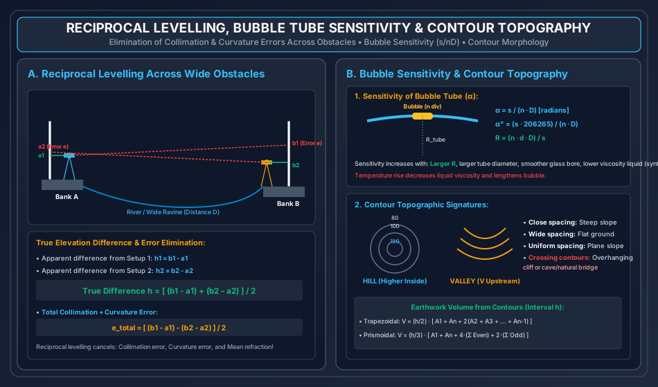
The sensitivity of a spirit level vial is defined as the angle (in radians or arc-seconds) through which the longitudinal axis of the tube must be tilted to cause the bubble to move through one standard division ():
Where:
- = Staff intercept difference between tilted and centered bubble positions ().
- = Number of vial graduations through which the bubble shifted.
- = Horizontal distance from instrument to staff ().
- = Linear length of one division on the vial scale ().
3. Step-by-Step Analytical Derivations & Mechanisms
3.1 Derivation of Earth Curvature Correction ()
Let be the center of the spherical Earth of radius . Let a level instrument be set up at station with telescope height establishing a tangent horizontal line of sight of length . Let be a point on the spherical level surface at distance .
                Horizontal Line of Sight (Tangent)
            A ────────────────────────────────────────► B'
            │                                         /
            │                                        /
            │ R                                     / R + Cc
            │                                      /
            │                                     /
            ▼                                    ▼
            O ────────────────────────────────── B (Level Geoid)
- In the right-angled triangle :
- Since , , and :
- Expanding the left-hand side:
- Canceling and recognizing that (since is a few centimeters/meters while ):
- Substituting , and expressing distance in kilometers ():
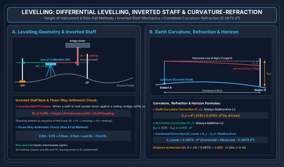
- Sign Mechanism: Because the horizontal line of sight diverges upward above the curved level line, the cross-hairs strike the staff at a reading higher than the true level intercept. Therefore, the curvature correction is strictly subtractive from the staff reading:
3.2 Atmospheric Refraction Mechanics ()
Because air density decreases with altitude, rays of light traversing the lower atmosphere pass through progressively denser air layers near the ground. By Snell's Law of refraction, the optical ray curves continuously downward toward the Earth's surface (concave downward), striking the staff below the geometrical tangent line:
- Under average atmospheric temperature and pressure gradients, the radius of curvature of the refracted light ray () is approximately times the radius of the Earth ().
- The refraction correction is therefore:
- Because refraction bends the ray downward, the staff intercept is lowered. Thus, refraction correction is additive to the staff reading:
- Net Combined Correction ():
3.3 Mathematical Proof of Error Elimination in Reciprocal Levelling
Let stations and be separated by a wide obstacle of width . Let the true difference in elevation between and be (assuming is higher than ). Let be the combined total error in staff reading across distance due to:
- Instrumental collimation error ()
- Earth curvature ()
- Atmospheric refraction ()
  Setup 1 (Near A):
  Staff at A (distance ~ 0):  Reading a1 = True reading
  Staff at B (distance D):    Reading b1 = True reading + e

  Setup 2 (Near B):
  Staff at A (distance D):    Reading a2 = True reading + e
  Staff at B (distance ~ 0):  Reading b2 = True reading
- From Instrument Setup 1 (Near A):
- Sighting on Staff is very close; error is zero: .
- Sighting on Staff spans distance : .
- Apparent elevation difference:
- From Instrument Setup 2 (Near B):
- Sighting on Staff is very close; error is zero: .
- Sighting on Staff spans distance : .
- Apparent elevation difference:
- Averaging the Two Apparent Differences: Mathematical Proof: The error term and cancel out completely, yielding the exact true elevation difference regardless of the magnitude of collimation error or Earth curvature!
4. Field Levelling Operations: Setup, Backsight, Foresight & Inverted Staff
4.1 Step-by-Step Field Procedure
- Instrument Setup & Temporary Adjustments:
- Setting up tripod on firm ground; leveling approximately by legs.
- Precision leveling using three footscrews: Align telescope parallel to two footscrews, turn screws equally in opposite directions until bubble is centered. Rotate telescope over third screw and center. Rotate to verify permanent adjustment.
- Elimination of parallax: Focus eyepiece against white paper until cross-hairs appear distinct and black; focus objective screw onto distant staff until relative motion between cross-hairs and image vanishes.
- Backsight (BS): The very first reading taken after setting up the instrument at any position, always sighted onto a station of known Reduced Level (Benchmark or Change Point).
- Intermediate Sight (IS): All readings taken between the backsight and foresight from the same instrument setup on points whose elevations are desired.
- Foresight (FS): The final reading taken from an instrument setup before moving the instrument to a new change point.
- Change Point / Turning Point (CP / TP): A stable, unyielding physical point on which both a foresight (from current station) and a backsight (from next station) are observed, carrying the vertical datum forward.
4.2 Inverted Staff Mechanics (Ceilings & Bridge Soffits)
When determining the elevation of points located above the line of collimation (e.g., bridge girder undersides, building ceilings, tunnel crown arches, road over-bridge clearances):
- The levelling staff is held upside down with its zero base resting firmly against the underside of the structural element.
- In the field book, the staff reading is entered with a negative sign (e.g., ).
- Mathematical Reduction: (The elevation of the overhead point equals the Height of Instrument PLUS the staff reading).
5. Errors in Levelling: Collimation Error & Two-Peg Test Calibration
5.1 Collimation Error
Collimation error occurs when the line of collimation is not strictly parallel to the axis of the bubble tube. When the bubble is centered, the line of sight tilts slightly upward or downward by an inclination angle .
- If foresight and backsight distances are strictly balanced (), the collimation error is identical on both sights () and cancels out completely:
- When sights are unbalanced (), collimation error accumulates rapidly.
5.2 The Two-Peg Test (Collimation Calibration Protocol)
  Peg A                                                       Peg B
    ●───────────────────────────────●───────────────────────────●
   Staff A                     Level 1 (Midway)               Staff B
                               D1 = D2 = 30 m
- Two pegs and are driven into the ground at a distance apart.
- Step 1: The level is set up exactly midway between and ().
- Read staff at () and staff at ().
- Because distances are perfectly balanced, errors cancel:
- Step 2: The level is moved and set up on the line close to peg (or outside at distance ).
- Read staff at () and staff at ().
- Apparent difference: .
- Collimation Error per Unit Distance ():
- Adjustment: The correct reading to be observed on distant staff is computed: With the bubble centered, the horizontal cross-hair is adjusted using the diaphragm reticle capstan screws until it reads .
6. Reciprocal Levelling: Precision Across Rivers & Ravines
When balancing sights is impossible (e.g., crossing a river of width ), reciprocal levelling eliminates:
- Permanent instrumental collimation error.
- Earth's spheroidal curvature error.
- Mean atmospheric refraction error (assuming temperature and humidity gradients over the water surface remain stable between the two observations).
Important Limitation: Reciprocal levelling does NOT eliminate refraction errors if the atmospheric temperature gradient over the river changes significantly between the morning and afternoon observations. Observations should be executed simultaneously using two matched levels and two observers if maximum geodetic precision is required.
7. Sensitivity of Spirit Level & Bubble Tube Mechanics
7.1 Physics of the Bubble Vial
A level tube consists of a sealed glass tube internally ground to a circular longitudinal arc of large radius () and filled with a low-viscosity, low-freezing-point liquid (synthetic ether, alcohol, or chloroform) leaving a small vapor bubble.
- Graduations: The glass surface is etched with divisions of length spaced symmetrically from the center.
- Factors Increasing Sensitivity:
- Radius of Curvature (): Greater radius of curvature produces higher sensitivity ().
- Internal Diameter of Vial: Larger diameter increases bubble stability and responsiveness.
- Viscosity of Liquid: Lower viscosity permits faster, frictionless bubble movement.
- Smoothness of Glass Bore: Highly polished internal tube minimizes boundary drag.
- Length of Bubble: Longer bubbles are more sensitive than very short bubbles.
- Effect of Temperature: An increase in temperature causes the liquid to expand, shortening the vapor bubble length and slightly reducing responsiveness.
8. Contouring: Definitions, Characteristics & Volumetric Computations
8.1 Fundamental Definitions
- Contour Line: An imaginary line on the ground surface connecting points of equal Reduced Level (elevation).
- Contour Interval: The constant vertical distance between two consecutive contour lines on a map.
- Sized based on: Scale of map, purpose of survey, extent of area, and available budget.
- Flat terrain: ; Rolling country: ; Mountainous terrain: .
- Horizontal Equivalent: The horizontal ground distance between two consecutive contours. Varies inversely with the steepness of the terrain.
8.2 The Ten Cardinal Topographic Characteristics of Contours
- All points on a contour line possess the identical Reduced Level.
- Flat ground is indicated by widely spaced contours; steep ground is indicated by closely spaced contours.
- A uniform slope is represented by equally spaced contour lines.
- Closed contour lines with higher values inside indicate a Hill or Summit.
- Closed contour lines with lower values inside indicate a Pond, Depression, or Lake Basin.
- Contour lines cross ridge lines and valley lines at right angles ().
- Ridge Line: Contours form U-shaped loops with the convex curve pointing downhill (towards lower elevation).
- Valley Line: Contours form V-shaped loops with the sharp vertex pointing upstream (towards higher elevation).
- Contour lines cannot cross or intersect each other, EXCEPT in the rare physical cases of an Overhanging Cliff or a Cave / Natural Rock Bridge.
- Contour lines cannot merge into a single line, EXCEPT in the case of a Vertical Cliff.
8.3 Reservoir Capacity & Earthwork Volume Computations
For a reservoir mapped with contours at uniform vertical interval , enclosing areas :
- Trapezoidal Rule (Average End Area Method):
- Prismoidal Rule (Simpson's Rule for Earthwork): (Note: Prismoidal rule requires an odd number of cross-sectional contour areas; gives higher volume precision; Prismoidal volume is generally smaller than Trapezoidal volume due to positive prismoidal correction: ).
9. Embedded Technical Visualizations & Diagrams
9.1 Differential Levelling Field Methods, Inverted Staff & Curvature-Refraction
The spatial configuration of Height of Instrument and Rise-and-Fall field levelling, the sign mechanics of inverted staff readings on bridge girders, and the combined curvature-refraction divergence are presented below.
9.2 Reciprocal Levelling Geometry, Bubble Tube Sensitivity & Topographic Contours
The exact error cancellation geometry of reciprocal levelling across rivers, the optical geometry of bubble tube sensitivity, and the fundamental morphological signatures of contour maps are illustrated below.
10. Worked Analytical & Design Numerical Problems
Problem 1: Field Book Level Reduction via Rise-and-Fall Method (With Inverted Staff)
Statement: The following consecutive staff readings were observed during a levelling run across a highway corridor intersecting a railway over-bridge. The Reduced Level of Benchmark 1 is known to be :
- Station 1 (BM 1):
- Station 2:
- Station 3: (Staff held inverted against the bottom flange of a steel bridge girder!)
- Station 4 (Change Point 1): ,
- Station 5:
- Station 6 (Change Point 2): ,
- Station 7:
Perform complete reduction of levels using the Rise-and-Fall Method. Tabulate the field book, compute the Reduced Levels of all stations (including the bridge girder soffit), and apply the complete three-way arithmetic check.
Analytical Solution:
Step 1: Consecutive Reading Differences (Rise or Fall)
- Station 1 to Station 2:
- Station 2 to Station 3 (Inverted Staff):
- Station 3 to Station 4:
- Station 4 to Station 5:
- Station 5 to Station 6:
- Station 6 to Station 7:
Step 2: Level Book Tabulation & Reduced Levels
| Station | BS (m) | IS (m) | FS (m) | Rise (m) | Fall (m) | Reduced Level (m) | Remarks |
|---|---|---|---|---|---|---|---|
| 1 | — | — | — | — | BM 1 | ||
| 2 | — | — | — | Ground point | |||
| 3 | — | — | — | Bridge Girder Soffit (Inverted) | |||
| 4 | — | — | Change Point 1 | ||||
| 5 | — | — | — | Ground point | |||
| 6 | — | — | Change Point 2 | ||||
| 7 | — | — | — | Final Station |
Step 3: Three-Way Arithmetic Check Verification
- Sum of Backsights:
- Sum of Foresights:
- Sum of Rises and Falls:
- Difference in End Elevations:
Problem 2: Reciprocal Levelling Across a Wide River
Statement: In levelling across a wide river channel of width (), reciprocal observations were conducted between two benchmarks and :
- Instrument set up near : Staff reading on , Staff reading on .
- Instrument set up near : Staff reading on , Staff reading on .
- Reduced Level of Benchmark is known to be .
Determine:
- The true difference in elevation between and , and state which station is lower.
- The true Reduced Level of Benchmark .
- The combined curvature and refraction error () across the river span.
- The instrumental collimation error () of the level, and determine whether the line of collimation is inclined upward or downward (both in linear millimetres and in angular seconds).
Analytical Solution:
Step 1: True Elevation Difference () Apparent differences from both setups:
- Setup near :
- Setup near :
True elevation difference:
Step 2: True Reduced Level of Benchmark
Step 3: Combined Curvature and Refraction Error () Across distance :
Step 4: Total Error & Instrumental Collimation Error Total error across distance :
Since total error :
Interpretation: The negative sign indicates that the line of collimation is inclined downward by over the distance. Angular tilt of collimation:
Problem 3: Sensitivity of Bubble Tube & Radius of Curvature
Statement: In a two-peg test to determine the sensitivity of the spirit level vial of an engineer's tilting level, the instrument was sighted onto a vertical levelling staff held at a distance of .
- When the bubble was centered, the staff reading was .
- The bubble was then shifted off-center by using the footscrew, and the new staff reading was observed to be .
- The length of one graduation division etched on the vial is ().
Compute:
- The staff intercept ().
- The sensitivity of the bubble tube in radians and in angular arc-seconds ().
- The internal radius of curvature of the bubble tube vial ().
Analytical Solution:
Step 1: Staff Intercept ()
Step 2: Sensitivity in Radians & Arc-Seconds Given , , :
Converting to arc-seconds:
Step 3: Internal Radius of Curvature of the Tube () Using the circular arc relation :
11. Cross-Exam Synthesis Matrix
| Exam | High-Frequency Conceptual Focus | Typical Calculation Types | Priority Traps & Critical Nuances |
|---|---|---|---|
| GATE CE | • Combined curvature & refraction () • Distance to visible horizon () • Reciprocal levelling true difference & error • Sensitivity of bubble tube () |
• Numerical Answer Type (NAT) reciprocal levelling • Missing entries in levelling field book • Inverted staff ceiling elevation |
• Curvature correction is SUBTRACTIVE from staff reading, which INCREASES the Reduced Level! • Inverted staff reading MUST be entered as NEGATIVE: . • Distance in MUST be in kilometers, result is in meters! |
| UPSC ESE | • Full derivation of and • Full proof of reciprocal levelling error cancellation • Two-Peg test calibration protocol • Simpson's Prismoidal vs Trapezoidal earthwork |
• Conventional 15-mark field book reduction (Rise & Fall) • Two-peg test collimation adjustment calculation • Reservoir storage volume from contour map |
• Rise-and-Fall method checks intermediate sights; HI method does NOT check intermediate sights! • Prismoidal rule requires an ODD number of contour areas. • Trapezoidal earthwork always overestimates volume compared to Prismoidal rule. |
| SSC JE / RRB JE | • Definition of Backsight, Foresight, Change point • Three-way arithmetic check formula • Contour characteristics (Ridge V-shape vs Valley U-shape, Hill vs Depression) • Contour interval vs Horizontal equivalent |
• Quick RL calculation () • Horizon distance () • Reciprocal difference formula () |
• Backsight is the FIRST reading; Foresight is the LAST reading. • A Change Point has BOTH a Foresight and a Backsight. • Overhanging cliff is the ONLY feature where contours cross each other. |
| State AE / PSU | • Sensitivity factors of bubble tube (, viscosity, temperature) • Parallax elimination (eyepiece and objective focusing) • Line of collimation vs axis of telescope • Contour interpolation methods (Estimation, Arithmetic, Graphical) |
• Sensitivity and radius • Curvature error for a given sight distance • True staff reading after curvature correction |
• Sensitivity INCREASES with larger radius , but DECREASES with higher liquid viscosity. • Temperature rise shortens the bubble and lowers sensitivity. • Line of collimation is horizontal ONLY when bubble is centered and instrument is adjusted. |
12. Common Failure Modes, Collimation Drift Diagnostics & Forensic Engineering
12.1 Unbalanced Sight Distances & Cumulative Collimation Drift
- Failure Phenomenon: In a precision trunk sewer line survey, the terminal outfall elevation was recorded higher than design, causing the gravity sewer to slope backward, trapping raw sewage.
- Root Cause & Forensic Diagnosis:
- The level had an undetected collimation tilt of (line of sight inclined upward).
- The instrument operator consistently set up the level closer to the backsight staff () than the foresight staff () to save walking time.
- The unbalanced distance per setup accumulated error over 80 setups:
- Forensic Countermeasures:
- Strictly enforce equal backsight and foresight distances () by pacing or stadia hair checks.
- Perform weekly Two-Peg test calibrations.
12.2 Staff Mud Sinking at Change Points
- Failure Phenomenon: Severe closing error at the benchmark after a morning levelling run across agricultural loam.
- Root Cause: The staffman placed the staff base directly on soft soil at change points. While the surveyor walked forward to reposition the instrument, the staff base sank under its own weight, corrupting the subsequent backsight datum.
- Site Rule: Always bed a heavy cast-iron triangular Change Plate (Footplate) at every change point before sighting.
13. Practice Problems & Exam Drill Questions
Question 1 (GATE Style — NAT)
An observer standing on the deck of a ship above sea level can just see the top of a lighthouse beacon. If the height of the lighthouse beacon is above Mean Sea Level, the distance between the ship and the lighthouse in kilometers is: (Round off to two decimal places).
- Answer:
- Explanation:
- Horizon distance formula: .
- .
- .
- (or using ).
Question 2 (UPSC ESE Style — Conceptual Multiple Choice)
Which of the following statements regarding Levelling and Contouring is/are CORRECT?
- The Rise-and-Fall method provides an arithmetic check on Intermediate Sights, whereas the Height of Instrument method does not.
- In reciprocal levelling, curvature error, collimation error, and mean atmospheric refraction error are eliminated.
- The sensitivity of a bubble tube increases with a decrease in the radius of curvature of the vial.
- Overhanging cliffs are represented by intersecting contour lines.
- Options: (a) 1, 2, and 4 only (b) 1, 3, and 4 only (c) 2 and 3 only (d) 1, 2, 3, and 4
- Correct Answer: (a) 1, 2, and 4 only
- Explanation: Statement 3 is incorrect because sensitivity of a bubble tube increases with an increase (not decrease) in the radius of curvature of the vial (). Statements 1, 2, and 4 are entirely correct.
Question 3 (SSC JE / RRB JE Style — Quick Recall)
A contour line connecting points of equal elevation represents a ridge line if the contours form:
- Options: (a) V-shaped curves with vertex pointing upstream (b) U-shaped curves with convexity pointing downhill (c) Closed concentric circles with lower values inside (d) Parallel straight lines
- Correct Answer: (b) U-shaped curves with convexity pointing downhill
- Explanation: A ridge line is characterized by U-shaped contour curves with the loop pointing towards lower elevation (downhill). Valley lines have V-shaped curves pointing towards higher elevation (upstream).
14. Comprehensive Technical Reference & Cross-Topic Linkages
Inter-Topic Knowledge Mapping
- Upstream Linkages:
SURV-01: Earth curvature, geodetic datums, and standard measurement error models.FM-01: Hydrostatic pressure, free liquid surfaces, and equipotential gravity fields.
- Concurrent & Downstream Linkages:
SURV-04: Theodolite vertical circle angles and trigonometric levelling ().SURV-05: Tacheometric distance and elevation formulas ().SURV-06: Digital Levels, bar-code invar staffs, LiDAR digital elevation models (DEM), and GNSS ellipsoidal-to-orthometric height geoid modeling ().
Standard Code References
- IS 1492 / IS 2231: Specification for Dumpy Levels and Tilting Levels, Bureau of Indian Standards.
- IS 3951: Specification for Levelling Staves (Telescopic & Folding).
- Survey of India: Levelling Manual and Instructions for Geodetic Levelling, Dehradun.
- USGS: Topographic Instructions: Levelling Procedures and Quality Control.