ENV-05 Chapter 05 · Biological Wastewater Treatment

Biological Wastewater Treatment (ASP, Monod Kinetics, Trickling Filters, UASB & Septic Tanks)

In this chapter (1 topics)
On this page
  1. 1. Topic Title & Authoritative References
  2. 2. Prerequisites & Learning Objectives
  3. Prerequisites
  4. Learning Objectives
  5. 3. Biological Treatment Fundamentals: Suspended vs Attached Growth
  6. 4. Microbial Growth Kinetics & The Monod Model
  7. 4.1 The Monod Empirical Growth Model
  8. 4.2 Biomass Synthesis & Endogenous Respiration Rates
  9. 5. Activated Sludge Process (ASP) Design & Control Metrics
  10. 5.1 Food-to-Microorganism Ratio (F/M)
  11. 5.2 Mean Cell Residence Time (MCRT / Sludge Age, θc)
  12. 5.3 Biomass Mass Balance Governing Equation
  13. 5.4 Sludge Recirculation Ratio (R = Qr / Q)
  14. 5.5 Net Daily Sludge Production (Px)
  15. 5.6 Theoretical Oxygen Requirement
  16. 5.7 Sludge Volume Index (SVI) Diagnostics
  17. 6. Trickling Filters: Attached-Growth Biofilm Dynamics & NRC Formulation
  18. 6.1 Physical Construction & Biofilm Ecology
  19. 6.2 Recirculation Hydraulics & Recirculation Factor (F)
  20. 6.3 National Research Council (NRC) Empirical Formulations
  21. 7. Anaerobic Treatment: UASB Reactors, Septic Tanks & Oxidation Ponds
  22. 7.1 Biochemical Pathways of Anaerobic Digestion
  23. 7.2 Upflow Anaerobic Sludge Blanket (UASB) Reactors
  24. 7.3 Septic Tanks & Soil Absorption Systems (IS 2470)
  25. 8. Advanced Biological Systems & Modifications
  26. 9. Step-by-Step Analytical Derivations
  27. 9.1 Derivation of Biomass Mass Balance in Complete-Mix ASP
  28. 9.2 Derivation of Return Sludge Recirculation Ratio (R)
  29. 9.3 Derivation of Net Biomass Production (Px) & Observed Yield (Yobs)
  30. 10. Solved Numerical Example 1: Activated Sludge Process Complete Design
  31. Problem Statement
  32. Complete Analytical Solution
  33. 11. Solved Numerical Example 2: High-Rate Trickling Filter Design via NRC Formula
  34. Problem Statement
  35. Complete Analytical Solution
  36. 12. Solved Numerical Example 3: Septic Tank & Soil Soak Pit Design (IS 2470)
  37. Problem Statement
  38. Complete Analytical Solution
  39. 13. Common Misconceptions & Exam Traps
  40. 14. Quick Revision Summary & Formula Sheet
  41. 14.1 Governing Mathematical Formulas
  42. 14.2 High-Yield Exam Memorization Matrix

1. Topic Title & Authoritative References

Title: Principles, Biological Mechanics, Microbial Growth Kinetics, Complete-Mix Activated Sludge (CMAS) Design & Control Metrics, Attached-Growth Trickling Filters (NRC Kinetics & Recirculation), High-Rate Anaerobic Reactors (UASB Technology), Septic Tanks & Soil Absorption Systems (IS 2470), and Oxidation Ponds.
Primary Standards & Authoritative Specifications:

  • CPHEEO Manual (2013 / 2024 update): Manual on Sewerage and Sewage Treatment Systems (Part A: Engineering; Part B: O&M), Ministry of Housing and Urban Affairs, Government of India.
  • IS 2470 (Part 1):1985: Code of Practice for Installation of Septic Tanks: Design Criteria and Construction.
  • IS 2470 (Part 2):1985: Code of Practice for Installation of Septic Tanks: Secondary Treatment and Disposal of Effluent.
  • Metcalf & Eddy / AECOM (2014): Wastewater Engineering: Treatment and Resource Recovery (5th Edition), McGraw-Hill Education.
  • Grady, C. P. L., Daigger, G. T., Love, N. G., & Mosquera-Corral, A. (2011): Biological Wastewater Treatment (3rd Edition), CRC Press.
  • WEF Manual of Practice No. 8: Design of Municipal Wastewater Treatment Plants, Water Environment Federation.

2. Prerequisites & Learning Objectives

Prerequisites

  • Microbiology & biochemistry: Heterotrophic oxidation, autotrophic nitrification, cellular chemical formula (C5H7NO2\text{C}_5\text{H}_7\text{NO}_2), endogenous respiration, enzyme-substrate Michaelis-Menten kinetics.
  • Reactor engineering: Continuous stirred tank reactors (CSTR / CMAS), plug flow reactors (PFR), steady-state conservation of mass for soluble substrate and active biomass.
  • Environmental quality metrics: 5-day Biochemical Oxygen Demand (BOD5\text{BOD}_5), Total Suspended Solids (TSS), Volatile Suspended Solids (VSS), Mixed Liquor Suspended Solids (MLSS), and Mixed Liquor Volatile Suspended Solids (MLVSS).

Learning Objectives

  1. Categorize biological wastewater treatment systems into suspended-growth and attached-growth processes under aerobic, anoxic, and anaerobic redox environments.
  2. Formulate the Monod microbial growth model, identifying maximum specific growth rate (μmax\mu_{\text{max}}), half-velocity constant (KsK_s), endogenous decay rate (kdk_d), and true biomass yield (YY).
  3. Derive the complete mass balance equations for a Complete-Mix Activated Sludge (CMAS) process with sludge return, establishing analytical relations for Hydraulic Retention Time (HRT/θHRT / \theta), Mean Cell Residence Time (MCRT / θc\theta_c), and Food-to-Microorganism ratio (F/MF/M).
  4. Calculate return sludge recirculation ratio (R=Qr/QR = Q_r/Q), daily waste sludge mass (PxP_x), required aeration tank volume, and theoretical oxygen requirements for carbonaceous oxidation and endogenous respiration.
  5. Diagnose secondary clarifier operating troubles using the Sludge Volume Index (SVI), differentiating between filamentous sludge bulking and sludge rising caused by secondary denitrification.
  6. Design high-rate trickling filters using the National Research Council (NRC) equations, sizing filter bed volume, rotary distributors, and recirculation factors (FF).
  7. Model anaerobic decomposition pathways (hydrolysis, acidogenesis, acetogenesis, methanogenesis) and size Upflow Anaerobic Sludge Blanket (UASB) reactors, septic tanks, and soak pits per IS 2470 standards.

3. Biological Treatment Fundamentals: Suspended vs Attached Growth

Biological wastewater treatment exploits microbial consortia to coagulate and remove non-settleable colloidal solids and oxidize dissolved organic substrate into stable, innocuous cellular biomass and gas end-products.

Classification Attribute Suspended Growth Systems (e.g., ASP, SBR, Aerated Lagoons) Attached Growth / Fixed-Film Systems (e.g., Trickling Filters, RBC, MBBR)
Microbial Habitat Biomass grows as suspended flocculent flocs in liquid culture agitated by aeration or mechanical mixing. Biomass forms a sedentary biofilm / gelatinous slime layer attached to inert solid packing media (stones, plastic).
Oxygen / Redox Supply Mechanical surface aerators or bottom submerged fine-bubble diffusers continuously transfer dissolved oxygen. Natural counter-current air draft circulating through bed voids due to thermal chimney effect between air and sewage.
Hydraulic Shock Resistance Moderate; susceptible to hydraulic wash-out of biomass flocs if secondary clarifier surface overflow rate is exceeded. High; sedentary biofilm cannot be washed out easily; highly resilient to intermittent toxic and organic surge loads.
Sludge Recycling Mandatory: settled active sludge from secondary clarifier is continuously recycled (QrQ_r) to maintain high MLSS. Optional: recirculation is employed to dilute influent BOD and maintain hydraulic wetting, not to return active biomass.
Operating Footprint & Cost Compact footprint; high electrical energy consumption for compressed air blowers; requires skilled operational control. Larger footprint (stone media); low electrical power consumption (gravity trickling); robust, minimal maintenance.

4. Microbial Growth Kinetics & The Monod Model

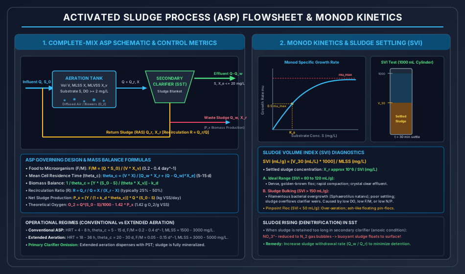
Activated Sludge Process Flowsheet & Monod Kinetics

4.1 The Monod Empirical Growth Model

The specific growth rate (μ\mu, day−1\text{day}^{-1}) of bacterial biomass depends hyperbolically on the concentration of the growth-limiting substrate (SS, mg/L\text{mg/L}):

μ=μmaxSKs+S\mu = \mu_{\text{max}} \frac{S}{K_s + S}

Where:

  • μmax=\mu_{\text{max}} = maximum specific growth rate (day−1\text{day}^{-1}).
  • Ks=K_s = half-velocity constant (mg/L\text{mg/L}), defined as the substrate concentration at which μ=0.50 μmax\mu = 0.50\,\mu_{\text{max}}.
  • S=S = soluble limiting substrate concentration in the reactor (mg/L\text{mg/L}).

Limiting Kinetic Regimes

  1. High Substrate Concentration (S≫KsS \gg K_s): μ≈μmax(Zero-order kinetics with respect to substrate)\mu \approx \mu_{\text{max}} \quad (\text{Zero-order kinetics with respect to substrate}) Observed in the inlet zones of plug-flow aeration tanks.
  2. Low Substrate Concentration (S≪KsS \ll K_s): μ≈(μmaxKs)S(First-order kinetics with respect to substrate)\mu \approx \left(\frac{\mu_{\text{max}}}{K_s}\right) S \quad (\text{First-order kinetics with respect to substrate}) Governs conventional complete-mix activated sludge reactors and effluent polishing.

4.2 Biomass Synthesis & Endogenous Respiration Rates

The gross rate of biomass synthesis (rg,synr_{g,\text{syn}}) is directly linked to the rate of substrate utilization (rsur_{su}) through the synthesis yield coefficient (YY):

rg,syn=−Y⋅rsu=Y(μmaxXSKs+S)r_{g,\text{syn}} = -Y \cdot r_{su} = Y \left( \frac{\mu_{\text{max}} X S}{K_s + S} \right)

Simultaneously, active biomass undergoes continuous auto-oxidation and cellular lysis (endogenous decay):

rdecay=−kd⋅Xr_{\text{decay}} = -k_d \cdot X

The net rate of active biomass growth (rgr_g) is therefore:

rg=Y⋅rsu−kd⋅X=(μ−kd)Xr_g = Y \cdot r_{su} - k_d \cdot X = (\mu - k_d) X

Where:

  • X=X = active microbial biomass concentration (mg VSS/L\text{mg VSS/L}).
  • Y=Y = true biomass yield coefficient (mg VSS synthesized / mg BOD5 consumed\text{mg VSS synthesized / mg BOD}_5 \text{ consumed}, typically 0.40−0.600.40 - 0.60).
  • kd=k_d = endogenous decay rate constant (day−1\text{day}^{-1}, typically 0.04−0.08 day−10.04 - 0.08\text{ day}^{-1} at 20∘C20^\circ\text{C}).

5. Activated Sludge Process (ASP) Design & Control Metrics

In a conventional Complete-Mix Activated Sludge (CMAS) system, settled wastewater (Q,S0Q, S_0) enters an aeration basin of volume VV, where it mixes with recycled sludge (Qr,XrQ_r, X_r). The mixed liquor is aerated for a hydraulic retention time θ\theta before overflowing into a secondary settling tank (SST).

5.1 Food-to-Microorganism Ratio (F/MF/M)

The F/MF/M ratio characterizes the organic loading rate applied per unit mass of active microorganisms in the aeration tank:

FM=Q⋅S0V⋅Xv(day−1 or kg BOD5/kg MLVSS⋅day)\frac{F}{M} = \frac{Q \cdot S_0}{V \cdot X_v} \quad (\text{day}^{-1} \text{ or kg BOD}_5 / \text{kg MLVSS}\cdot\text{day})

Where:

  • Q=Q = influent wastewater volumetric discharge (m3/day\text{m}^3/\text{day}).
  • S0=S_0 = influent BOD5\text{BOD}_5 after primary sedimentation (mg/L=g/m3\text{mg/L} = \text{g/m}^3).
  • V=V = volume of aeration tank (m3\text{m}^3).
  • Xv=X_v = Mixed Liquor Volatile Suspended Solids concentration (mg/L=g/m3\text{mg/L} = \text{g/m}^3), where Xv≈0.80×XX_v \approx 0.80 \times X (MLSS).
  • Typical Operational Range:
    • Conventional ASP: 0.20−0.40 day−10.20 - 0.40\text{ day}^{-1}
    • Extended Aeration (Oxidation Ditch): 0.05−0.15 day−10.05 - 0.15\text{ day}^{-1}
    • High-Rate Aeration: 0.50−1.50 day−10.50 - 1.50\text{ day}^{-1}

5.2 Mean Cell Residence Time (MCRT / Sludge Age, θc\theta_c)

The average duration (in days) that an active microbial cell resides within the treatment system before being wasted:

θc=Total Biomass in SystemTotal Biomass Lost per Day=V⋅XQw⋅Xr+(Q−Qw)Xe≈V⋅XQw⋅Xr\theta_c = \frac{\text{Total Biomass in System}}{\text{Total Biomass Lost per Day}} = \frac{V \cdot X}{Q_w \cdot X_r + (Q - Q_w) X_e} \approx \frac{V \cdot X}{Q_w \cdot X_r}

Where:

  • Qw=Q_w = waste sludge volumetric flow rate (m3/day\text{m}^3/\text{day}).
  • Xr=X_r = return / underflow sludge concentration (mg/L\text{mg/L}).
  • Xe=X_e = effluent suspended solids concentration (mg/L≤15−20 mg/L\text{mg/L} \le 15 - 20\text{ mg/L}).
  • Typical Range:
    • Conventional ASP: 5−15 days5 - 15\text{ days}
    • Extended Aeration: 20−30 days20 - 30\text{ days}

5.3 Biomass Mass Balance Governing Equation

At steady state, the rate of net biomass synthesis in the reactor equals the rate of biomass wasting from the system:

1θc=Y(S0−S)θ⋅Xv−kd=Y⋅U−kd\frac{1}{\theta_c} = \frac{Y(S_0 - S)}{\theta \cdot X_v} - k_d = Y \cdot U - k_d

Where:

  • θ=V/Q=\theta = V / Q = Hydraulic Retention Time (HRTHRT, typically 4−8 hours4 - 8\text{ hours}).
  • U=Q(S0−S)VXv=U = \frac{Q(S_0 - S)}{V X_v} = specific substrate utilization rate (day−1\text{day}^{-1}).

Solving for reactor volume VV:

V=θc⋅Q⋅Y(S0−S)Xv(1+kd⋅θc)V = \frac{\theta_c \cdot Q \cdot Y (S_0 - S)}{X_v (1 + k_d \cdot \theta_c)}

5.4 Sludge Recirculation Ratio (R=Qr/QR = Q_r / Q)

Applying a mass balance of solids around the aeration basin inlet junction:

(Q+Qr)X=Qr⋅Xr  ⟹  Q⋅X+Qr⋅X=Qr⋅Xr(Q + Q_r) X = Q_r \cdot X_r \implies Q \cdot X + Q_r \cdot X = Q_r \cdot X_r Q⋅X=Qr(Xr−X)  ⟹  R=QrQ=XXr−XQ \cdot X = Q_r (X_r - X) \implies R = \frac{Q_r}{Q} = \frac{X}{X_r - X}
  • For X=3,000 mg/LX = 3,000\text{ mg/L} and Xr=10,000 mg/LX_r = 10,000\text{ mg/L}: R=3,00010,000−3,000=3,0007,000=0.4286=42.86%R = \frac{3,000}{10,000 - 3,000} = \frac{3,000}{7,000} = 0.4286 = 42.86\%

5.5 Net Daily Sludge Production (PxP_x)

The net mass of biological volatile solids generated per day that must be purged from the system:

Px,vss=Yobs⋅Q(S0−S)×10−3(kg VSS/day)P_{x,\text{vss}} = Y_{\text{obs}} \cdot Q (S_0 - S) \times 10^{-3} \quad (\text{kg VSS/day}) Yobs=Y1+kd⋅θcY_{\text{obs}} = \frac{Y}{1 + k_d \cdot \theta_c} Px,total=Px,vss0.80(kg TSS/day)P_{x,\text{total}} = \frac{P_{x,\text{vss}}}{0.80} \quad (\text{kg TSS/day})

5.6 Theoretical Oxygen Requirement

Oxygen is consumed for carbonaceous substrate oxidation minus the oxygen equivalent of unoxidized biomass purged as waste sludge:

Total O2 (kg/day)=Q(S0−S)1000⋅f−1.42⋅Px,vss\text{Total } \text{O}_2 \text{ (kg/day)} = \frac{Q(S_0 - S)}{1000 \cdot f} - 1.42 \cdot P_{x,\text{vss}}

Where:

  • f=BOD5/BODu≈0.68f = \text{BOD}_5 / \text{BOD}_u \approx 0.68.
  • 1.42=1.42 = stoichiometric mass of O2\text{O}_2 consumed per unit mass of biological cell tissue (C5H7NO2+5 O2→5 CO2+2 H2O+NH3  ⟹  160113=1.416≈1.42\text{C}_5\text{H}_7\text{NO}_2 + 5\,\text{O}_2 \to 5\,\text{CO}_2 + 2\,\text{H}_2\text{O} + \text{NH}_3 \implies \frac{160}{113} = 1.416 \approx 1.42).

5.7 Sludge Volume Index (SVI) Diagnostics

The volume in milliliters occupied by 1.0 gram1.0\text{ gram} of activated sludge after settling for 30 minutes30\text{ minutes} in a 1000 mL1000\text{ mL} graduated cylinder:

SVI (mL/g)=V30 (mL/L)×1000MLSS (mg/L)\text{SVI (mL/g)} = \frac{V_{30} \text{ (mL/L)} \times 1000}{\text{MLSS (mg/L)}}

Return sludge concentration estimate:

Xr≈106SVI(mg/L)X_r \approx \frac{10^6}{\text{SVI}} \quad (\text{mg/L})
SVI Range (mL/g\text{mL/g}) Settling Characteristics & Physical Diagnosis Operational Status
<50< 50 Rapidly settling, dense pin-point flocs; leaves turbid supernatant with fine uncoagulated particles. Over-aeration, high MCRT, low F/MF/M.
80−12080 - 120 Ideal compacting golden-brown floc; rapid separation; crystal clear effluent. Excellent conventional operating state.
120−150120 - 150 Slow compaction; loose floc structure; acceptable if clarifier area is generous. Upper threshold of stable operation.
>150> 150 Sludge Bulking: Excessive filamentous bacteria (Sphaerotilus natans, Microthrix parvicella); sludge does not compact; overflows effluent weirs. Caused by low DO (<2 mg/L<2\text{ mg/L}), low F/MF/M, nutrient deficiency (N, P\text{N, P}), or low pH.

Sludge Bulking vs Sludge Rising (Denitrification)

  • Sludge Bulking: Sludge flocs fail to settle due to filamentous mesh networks. Remedy: Chlorinate return sludge (2−5 kg Cl2/1000 kg MLSS2 - 5\text{ kg Cl}_2 / 1000\text{ kg MLSS}), boost aeration basin DO.
  • Sludge Rising: Sludge settles initially, but after 1−2 hours1 - 2\text{ hours} in secondary clarifier, large chunks float to the surface buoyed by tiny gas bubbles. Cause: Anoxic conditions in the clarifier blanket allow denitrifiers to reduce nitrate to nitrogen gas (2NO3−→N2↑2\text{NO}_3^- \to \text{N}_2 \uparrow). Remedy: Increase sludge withdrawal rate (Qw,QrQ_w, Q_r) to minimize clarifier sludge blanket detention time.

6. Trickling Filters: Attached-Growth Biofilm Dynamics & NRC Formulation

Trickling Filters & Anaerobic UASB Reactors

6.1 Physical Construction & Biofilm Ecology

A trickling filter consists of a circular shallow bed packed with coarse rock (25−100 mm25 - 100\text{ mm} granite/crushed stone) or structured synthetic PVC corrugated sheets, over which settled wastewater is distributed intermittently by rotating perforated spray arms.

  1. Active Slime Layer (Biofilm):
    • Microorganisms adhere to media surfaces forming a gelatinous biofilm (0.1−2.0 mm0.1 - 2.0\text{ mm} thick).
    • Outer Aerobic Zone: Heterotrophic bacteria, fungi, and protozoa absorb organic substrate and dissolved oxygen.
    • Inner Anaerobic Zone: As biofilm thickens, oxygen cannot penetrate beyond 0.1−0.2 mm0.1 - 0.2\text{ mm}; anaerobic fermentation occurs adjacent to the rock face, producing organic acids and H2S\text{H}_2\text{S}.
  2. Sloughing Mechanism:
    • As microorganisms at the media interface starve from lack of organic substrate, they lyse and lose cellular adhesion.
    • Wastewater shear washes the dead biomass off the media in clumps ("sloughing").
    • Sloughed biological solids are subsequently separated in a secondary settling tank (humus tank).

6.2 Recirculation Hydraulics & Recirculation Factor (FF)

Recirculation of clarified effluent around the trickling filter dilutes high influent BOD, maintains continuous wetting of the biofilm, and dampens peak organic surge loads.

Recirculation Ratio R=QrQ\text{Recirculation Ratio } R = \frac{Q_r}{Q} Recirculation Factor F=1+R(1+0.1⋅R)2\text{Recirculation Factor } F = \frac{1 + R}{(1 + 0.1 \cdot R)^2}

6.3 National Research Council (NRC) Empirical Formulations

Developed from performance data of military and municipal trickling filter plants treating domestic sewage:

1. Single-Stage Trickling Filter Efficiency (η1\eta_1)

η1=1001+0.443WV⋅F\eta_1 = \frac{100}{1 + 0.443 \sqrt{\frac{W}{V \cdot F}}}

Where:

  • η1=\eta_1 = BOD removal efficiency of first-stage filter and clarifier (%\%).
  • W=Q⋅S0×10−3=W = Q \cdot S_0 \times 10^{-3} = raw BOD5\text{BOD}_5 organic loading applied (kg/day\text{kg/day}).
  • V=V = volume of filter packing media (m3\text{m}^3).
  • F=F = recirculation factor (dimensionless).

2. Second-Stage Trickling Filter Efficiency (η2\eta_2)

Because the organic matter reaching the second-stage filter is significantly more recalcitrant (harder to biodegrade), a biological retarding factor 11−η1\frac{1}{1 - \eta_1} is incorporated:

η2=1001+(0.4431−η1)W2V2⋅F2\eta_2 = \frac{100}{1 + \left(\frac{0.443}{1 - \eta_1}\right) \sqrt{\frac{W_2}{V_2 \cdot F_2}}}

Where:

  • W2=(1−η1)W=W_2 = (1 - \eta_1) W = BOD load entering the second filter (kg/day\text{kg/day}).
  • V2=V_2 = volume of second-stage filter media (m3\text{m}^3).
  • F2=F_2 = recirculation factor of second stage.

7. Anaerobic Treatment: UASB Reactors, Septic Tanks & Oxidation Ponds

7.1 Biochemical Pathways of Anaerobic Digestion

Anaerobic degradation converts complex organic polymers into methane and carbon dioxide in four successive microbial stages:

  1. Hydrolysis: Extracellular enzymes hydrolyze insoluble polymers (proteins, carbohydrates, lipids) into soluble monomers (amino acids, monosaccharides, fatty acids).
  2. Acidogenesis: Acid-forming fermentative bacteria convert monomers into volatile fatty acids (acetate, propionate, butyrate), alcohols, H2\text{H}_2, and CO2\text{CO}_2.
  3. Acetogenesis: Acetogenic bacteria convert propionate and butyrate into acetate, CO2\text{CO}_2, and hydrogen gas (H2\text{H}_2).
  4. Methanogenesis: Strictly anaerobic archaea synthesize methane:
    • Acetoclastic Methanogens (70%70\% of methane): CH3COOH→CH4+CO2\text{CH}_3\text{COOH} \to \text{CH}_4 + \text{CO}_2
    • Hydrogenotrophic Methanogens (30%30\% of methane): CO2+4 H2→CH4+2 H2O\text{CO}_2 + 4\,\text{H}_2 \to \text{CH}_4 + 2\,\text{H}_2\text{O}

Theoretical Biogas Production

Stoichiometrically, the complete oxidation of 1 mole of methane1\text{ mole of methane} requires 2 moles of O22\text{ moles of }\text{O}_2 (64 g COD64\text{ g COD}):

CH4+2 O2→CO2+2 H2O\text{CH}_4 + 2\,\text{O}_2 \to \text{CO}_2 + 2\,\text{H}_2\text{O}

At Standard Temperature and Pressure (0∘C,1 atm0^\circ\text{C}, 1\text{ atm}), 1 mole of gas=22.414 L1\text{ mole of gas} = 22.414\text{ L}:

Methane Yield=22.414 L64 g COD=0.350 L CH4/g COD=0.35 m3 CH4/kg COD removed\text{Methane Yield} = \frac{22.414\text{ L}}{64\text{ g COD}} = 0.350\text{ L CH}_4 / \text{g COD} = 0.35\text{ m}^3 \text{ CH}_4 / \text{kg COD removed}

At 30∘C30^\circ\text{C} and 1 atm1\text{ atm}, the yield expands to 0.388 m3 CH4/kg COD removed0.388\text{ m}^3 \text{ CH}_4 / \text{kg COD removed}.

7.2 Upflow Anaerobic Sludge Blanket (UASB) Reactors

A high-rate anaerobic technology where wastewater flows upward through an expanded dense granular sludge bed (50−100 g/L50 - 100\text{ g/L} VSS).

  1. Granular Sludge Bed: Self-immobilized spherical biocatalytic granules (1−3 mm1 - 3\text{ mm} diameter) with high settleability (vs≥30−50 m/hv_s \ge 30 - 50\text{ m/h}).
  2. Gas-Liquid-Solid (GLS) Separator: Inverted conical or pyramidal hoods located in the upper reactor zone:
    • Biogas bubbles strike the deflector plates, separate from the liquid, and are collected in the gas dome.
    • Degassed sludge particles slide back into the lower blanket along the inclined deflector surfaces.
    • Clarified treated liquid overflows into peripheral discharge launders.
  3. Key Design Parameters:
    • Volumetric organic loading rate (OLR): 5−15 kg COD/m3⋅day5 - 15\text{ kg COD/m}^3\cdot\text{day}
    • Upflow velocity: vup=0.60−1.0 m/hv_{\text{up}} = 0.60 - 1.0\text{ m/h}
    • Hydraulic retention time: HRT=6−10 hoursHRT = 6 - 10\text{ hours}
    • Biogas composition: 65−70% CH465 - 70\% \text{ CH}_4, 30−35% CO230 - 35\% \text{ CO}_2.

7.3 Septic Tanks & Soil Absorption Systems (IS 2470)

A septic tank is a primary sedimentation tank combined with unheated, unmixed anaerobic sludge digestion for on-site sanitation.

  • Design Volume Balance: Vtotal=Vliquid+VsludgeV_{\text{total}} = V_{\text{liquid}} + V_{\text{sludge}}
    • Vliquid=Q×tdV_{\text{liquid}} = Q \times t_d, where tdt_d is the liquid detention period =24 to 48 hours= 24\text{ to } 48\text{ hours}.
    • Vsludge=Users×Sludge Accumulation Rate×Cleaning PeriodV_{\text{sludge}} = \text{Users} \times \text{Sludge Accumulation Rate} \times \text{Cleaning Period}.
    • IS 2470 standard sludge accumulation rate: 0.070 m3/person⋅year0.070\text{ m}^3/\text{person}\cdot\text{year} (70 L/person⋅year70\text{ L/person}\cdot\text{year}).
    • Cleaning / desludging frequency: 1 to 2 years1\text{ to } 2\text{ years}.
  • Geometry & Ratios:
    • Length-to-width ratio: L=(2 to 4)×BL = (2 \text{ to } 4) \times B (standard L/B=3L/B = 3).
    • Liquid depth: 1.0−1.8 m1.0 - 1.8\text{ m}.
    • Freeboard: minimum 0.30 m0.30\text{ m}.
    • Compartment partitioning: Hanging baffle or perforated divider wall located at 2/32/3 of the tank length from the inlet.
  • Effluent Disposal via Soak Pit / Dispersion Trench: The effluent application rate is governed by soil percolation tests (tt, minutes per cm drop): qeffluent=204t(L/m2⋅day, per IS 2470)q_{\text{effluent}} = \frac{204}{\sqrt{t}} \quad (\text{L/m}^2\cdot\text{day, per IS 2470}) qeffluent=130t(L/m2⋅day, per CPHEEO Manual)q_{\text{effluent}} = \frac{130}{\sqrt{t}} \quad (\text{L/m}^2\cdot\text{day, per CPHEEO Manual})

8. Advanced Biological Systems & Modifications

  1. Extended Aeration / Oxidation Ditch:
    • Operates in the endogenous respiration growth phase (F/M=0.05−0.15 day−1F/M = 0.05 - 0.15\text{ day}^{-1}, θc=20−30 days\theta_c = 20 - 30\text{ days}).
    • High hydraulic retention time (θ=18−36 hours\theta = 18 - 36\text{ hours}).
    • Eliminates the primary clarifier; waste sludge is already aerobically digested and mineralized.
  2. Sequencing Batch Reactor (SBR):
    • Time-oriented activated sludge process operating in a single reactor tank through cyclic sequential phases: Fill→React (Aeration)→Settle (Clarification)→Decant (Effluent Withdrawal)→Idle / Waste\text{Fill} \to \text{React (Aeration)} \to \text{Settle (Clarification)} \to \text{Decant (Effluent Withdrawal)} \to \text{Idle / Waste}
    • Eliminates separate secondary clarifiers and external return sludge pumping stations.
  3. Moving Bed Biofilm Reactor (MBBR):
    • Hybrid system combining suspended growth and attached growth: high surface area plastic carrier elements (K1/K3K1 / K3 media, 500−800 m2/m3500 - 800\text{ m}^2/\text{m}^3) are kept in continuous suspension in the aeration tank by coarse bubble diffusers.
  4. Membrane Bioreactor (MBR):
    • Combines biological degradation with submerged microfiltration / ultrafiltration hollow-fiber membranes (0.04−0.4 μm0.04 - 0.4\,\mu\text{m}).
    • Operates at exceptionally high MLSS (8,000−15,000 mg/L8,000 - 15,000\text{ mg/L}); completely eliminates secondary clarifiers, producing tertiary-quality permeate suitable for direct reuse.

9. Step-by-Step Analytical Derivations

9.1 Derivation of Biomass Mass Balance in Complete-Mix ASP

Consider a complete-mix activated sludge aeration tank of volume VV receiving influent flow QQ with substrate S0S_0 and negligible influent biomass (X0≈0X_0 \approx 0).
The mixed liquor volatile suspended solids (MLVSS) concentration inside the reactor is XvX_v. The reactor discharges into a secondary clarifier that separates treated effluent (Q−QwQ - Q_w, biomass XeX_e) from waste sludge (QwQ_w, biomass XrX_r).

Applying the conservation of biomass mass around the entire system boundary:

[Rate of Biomass Inflow]−[Rate of Biomass Outflow]+[Net Rate of Biomass Growth]=[Rate of Accumulation](1)\left[ \text{Rate of Biomass Inflow} \right] - \left[ \text{Rate of Biomass Outflow} \right] + \left[ \text{Net Rate of Biomass Growth} \right] = \left[ \text{Rate of Accumulation} \right] \tag{1}

At steady state, d(VXv)dt=0\frac{d(V X_v)}{dt} = 0:

0−[QwXr+(Q−Qw)Xe]+V⋅rg=0(2)0 - \left[ Q_w X_r + (Q - Q_w) X_e \right] + V \cdot r_g = 0 \tag{2}

Substitute net biomass growth rg=Y⋅rsu−kd⋅Xvr_g = Y \cdot r_{su} - k_d \cdot X_v:

QwXr+(Q−Qw)Xe=V[Y⋅rsu−kd⋅Xv](3)Q_w X_r + (Q - Q_w) X_e = V \left[ Y \cdot r_{su} - k_d \cdot X_v \right] \tag{3}

Divide both sides by V⋅XvV \cdot X_v:

QwXr+(Q−Qw)XeV⋅Xv=Y⋅rsuXv−kd(4)\frac{Q_w X_r + (Q - Q_w) X_e}{V \cdot X_v} = \frac{Y \cdot r_{su}}{X_v} - k_d \tag{4}

By definition, the Mean Cell Residence Time (θc\theta_c) is:

θc=V⋅XvQwXr+(Q−Qw)Xe  ⟹  1θc=QwXr+(Q−Qw)XeV⋅Xv(5)\theta_c = \frac{V \cdot X_v}{Q_w X_r + (Q - Q_w) X_e} \implies \frac{1}{\theta_c} = \frac{Q_w X_r + (Q - Q_w) X_e}{V \cdot X_v} \tag{5}

The substrate utilization rate across the aeration basin under steady-state mass balance is:

rsu=Q(S0−S)V(6)r_{su} = \frac{Q(S_0 - S)}{V} \tag{6}

Substitute Eq. (5) and Eq. (6) into Eq. (4):

1θc=Y⋅Q(S0−S)VXv−kd(7)\frac{1}{\theta_c} = \frac{Y \cdot \frac{Q(S_0 - S)}{V}}{X_v} - k_d \tag{7}

Recognizing that hydraulic retention time θ=V/Q\theta = V / Q:

1θc=Y(S0−S)θ⋅Xv−kd■(8)\frac{1}{\theta_c} = \frac{Y (S_0 - S)}{\theta \cdot X_v} - k_d \quad \blacksquare \tag{8}

9.2 Derivation of Return Sludge Recirculation Ratio (RR)

Consider the junction node where influent wastewater (Q,X0≈0Q, X_0 \approx 0) merges with return activated sludge (Qr,XrQ_r, X_r) just upstream of the aeration tank entrance:

Combined Flow Entering Aeration Tank=Q+Qr(1)\text{Combined Flow Entering Aeration Tank} = Q + Q_r \tag{1} Biomass Mass Flow Entering=Q⋅X0+Qr⋅Xr=Qr⋅Xr(2)\text{Biomass Mass Flow Entering} = Q \cdot X_0 + Q_r \cdot X_r = Q_r \cdot X_r \tag{2}

The biomass concentration immediately inside the aeration basin is the mixed liquor suspended solids (XX):

(Q+Qr)X=Qr⋅Xr(3)(Q + Q_r) X = Q_r \cdot X_r \tag{3}

Expanding the left side:

Q⋅X+Qr⋅X=Qr⋅Xr(4)Q \cdot X + Q_r \cdot X = Q_r \cdot X_r \tag{4}

Rearranging terms:

Q⋅X=Qr⋅Xr−Qr⋅X=Qr(Xr−X)(5)Q \cdot X = Q_r \cdot X_r - Q_r \cdot X = Q_r (X_r - X) \tag{5}

Dividing by Q(Xr−X)Q (X_r - X):

QrQ=XXr−X(6)\frac{Q_r}{Q} = \frac{X}{X_r - X} \tag{6}

Defining the recirculation ratio R=Qr/QR = Q_r / Q:

R=XXr−X■(7)R = \frac{X}{X_r - X} \quad \blacksquare \tag{7}

9.3 Derivation of Net Biomass Production (PxP_x) & Observed Yield (YobsY_{\text{obs}})

From the fundamental biomass balance derived in Section 9.1:

1θc=Y(S0−S)θ⋅Xv−kd(1)\frac{1}{\theta_c} = \frac{Y (S_0 - S)}{\theta \cdot X_v} - k_d \tag{1}

Add kdk_d to both sides:

1θc+kd=1+kd⋅θcθc=Y(S0−S)θ⋅Xv(2)\frac{1}{\theta_c} + k_d = \frac{1 + k_d \cdot \theta_c}{\theta_c} = \frac{Y (S_0 - S)}{\theta \cdot X_v} \tag{2}

Rearranging for the total active biomass in the aeration tank (VXvV X_v): Since θ=V/Q\theta = V / Q:

VXv=Y⋅Q(S0−S)⋅θc1+kd⋅θc(3)V X_v = \frac{Y \cdot Q (S_0 - S) \cdot \theta_c}{1 + k_d \cdot \theta_c} \tag{3}

The net daily mass of biomass wasted from the system (Px,vssP_{x,\text{vss}}) is:

Px,vss=VXvθc(4)P_{x,\text{vss}} = \frac{V X_v}{\theta_c} \tag{4}

Substitute Eq. (3) into Eq. (4):

Px,vss=1θc[Y⋅Q(S0−S)⋅θc1+kd⋅θc]=(Y1+kd⋅θc)Q(S0−S)(5)P_{x,\text{vss}} = \frac{1}{\theta_c} \left[ \frac{Y \cdot Q (S_0 - S) \cdot \theta_c}{1 + k_d \cdot \theta_c} \right] = \left( \frac{Y}{1 + k_d \cdot \theta_c} \right) Q (S_0 - S) \tag{5}

Defining the observed yield coefficient YobsY_{\text{obs}}:

Yobs=Y1+kd⋅θc(6)Y_{\text{obs}} = \frac{Y}{1 + k_d \cdot \theta_c} \tag{6} Px,vss=Yobs⋅Q(S0−S)■(7)P_{x,\text{vss}} = Y_{\text{obs}} \cdot Q (S_0 - S) \quad \blacksquare \tag{7}

10. Solved Numerical Example 1: Activated Sludge Process Complete Design

Problem Statement

A municipal wastewater treatment facility uses a conventional complete-mix activated sludge process to treat a design discharge of Q=15.0 MLD=15,000 m3/dayQ = 15.0\text{ MLD} = 15,000\text{ m}^3/\text{day}.
The raw municipal sewage has a BOD5\text{BOD}_5 of 200.0 mg/L200.0\text{ mg/L}, and the primary settling tank achieves 30.0%30.0\% BOD5\text{BOD}_5 reduction.
The statutory effluent quality standard specifies BOD5≤15.0 mg/L\text{BOD}_5 \le 15.0\text{ mg/L} and suspended solids Xe≤15.0 mg/LX_e \le 15.0\text{ mg/L}.

The aeration basin is operated at the following design parameters:

  • Mixed Liquor Suspended Solids (MLSS): X=3,000.0 mg/LX = 3,000.0\text{ mg/L}
  • Volatile fraction: MLVSS/MLSS=0.80  ⟹  Xv=2,400.0 mg/L\text{MLVSS} / \text{MLSS} = 0.80 \implies X_v = 2,400.0\text{ mg/L}
  • Mean Cell Residence Time (Sludge Age): θc=10.0 days\theta_c = 10.0\text{ days}
  • Return sludge concentration: Xr=10,000.0 mg/LX_r = 10,000.0\text{ mg/L}
  • Biological kinetic constants: Y=0.50 mg VSS / mg BOD5Y = 0.50\text{ mg VSS / mg BOD}_5, kd=0.050 day−1k_d = 0.050\text{ day}^{-1}

Calculate:

  1. The required aeration tank volume (VV) and Hydraulic Retention Time (HRT/θHRT / \theta in hours).
  2. The Food-to-Microorganism ratio (F/MF/M) on both MLVSS and MLSS bases.
  3. The sludge recirculation ratio (R=Qr/QR = Q_r/Q) and the recycled flow rate (QrQ_r in m3/day\text{m}^3/\text{day}).
  4. The daily waste activated sludge production (Px,vssP_{x,\text{vss}} and Px,totalP_{x,\text{total}} in kg/day\text{kg/day}) and the volumetric wastage flow rate (QwQ_w in m3/day\text{m}^3/\text{day}).

Complete Analytical Solution

1. Aeration Basin Volume (VV) and HRT (θ\theta)

Influent BOD5\text{BOD}_5 entering aeration basin after 30%30\% PST removal:

S0=200.0×(1−0.30)=140.0 mg/LS_0 = 200.0 \times (1 - 0.30) = 140.0\text{ mg/L}

Effluent substrate S=15.0 mg/L  ⟹  S0−S=140.0−15.0=125.0 mg/LS = 15.0\text{ mg/L} \implies S_0 - S = 140.0 - 15.0 = 125.0\text{ mg/L}.

Applying the biomass balance equation:

1θc=Y(S0−S)θ⋅Xv−kd\frac{1}{\theta_c} = \frac{Y(S_0 - S)}{\theta \cdot X_v} - k_d 110.0+0.050=0.100+0.050=0.150 day−1\frac{1}{10.0} + 0.050 = 0.100 + 0.050 = 0.150\text{ day}^{-1} Y(S0−S)θ⋅Xv=0.150\frac{Y(S_0 - S)}{\theta \cdot X_v} = 0.150

Solving for θ\theta:

θ=Y(S0−S)Xv×0.150=0.50×125.02,400.0×0.150=62.5360.0=0.17361 days\theta = \frac{Y(S_0 - S)}{X_v \times 0.150} = \frac{0.50 \times 125.0}{2,400.0 \times 0.150} = \frac{62.5}{360.0} = 0.17361\text{ days} HRT (hours)=0.17361×24.0=4.1667 hours≈4.17 hours\text{HRT (hours)} = 0.17361 \times 24.0 = 4.1667\text{ hours} \approx 4.17\text{ hours}

Aeration tank volume:

V=Q⋅θ=15,000 m3/day×0.17361 days=2,604.17 m3≈2,604.2 m3V = Q \cdot \theta = 15,000\text{ m}^3/\text{day} \times 0.17361\text{ days} = 2,604.17\text{ m}^3 \approx 2,604.2\text{ m}^3

2. Food-to-Microorganism Ratio (F/MF/M)

Total Daily BOD Applied=Q⋅S0=15,000 m3/day×140.0 g/m3=2,100,000 g/day=2,100.0 kg/day\text{Total Daily BOD Applied} = Q \cdot S_0 = 15,000\text{ m}^3/\text{day} \times 140.0\text{ g/m}^3 = 2,100,000\text{ g/day} = 2,100.0\text{ kg/day}
  • On MLVSS Basis (Xv=2,400 mg/LX_v = 2,400\text{ mg/L}):

    Total MLVSS Mass=V⋅Xv=2,604.17 m3×2.40 kg/m3=6,250.0 kg\text{Total MLVSS Mass} = V \cdot X_v = 2,604.17\text{ m}^3 \times 2.40\text{ kg/m}^3 = 6,250.0\text{ kg} FM=2,100.0 kg/day6,250.0 kg=0.336 day−1(0.336 kg BOD5/kg MLVSS⋅day)\frac{F}{M} = \frac{2,100.0\text{ kg/day}}{6,250.0\text{ kg}} = 0.336\text{ day}^{-1} \quad (0.336\text{ kg BOD}_5 / \text{kg MLVSS}\cdot\text{day})
  • On MLSS Basis (X=3,000 mg/LX = 3,000\text{ mg/L}):

    FMMLSS=2,100.02,604.17×3.0=2,100.07,812.5=0.2688≈0.269 day−1\frac{F}{M}_{\text{MLSS}} = \frac{2,100.0}{2,604.17 \times 3.0} = \frac{2,100.0}{7,812.5} = 0.2688 \approx 0.269\text{ day}^{-1}

3. Sludge Recirculation Ratio (RR) & Flow Rate (QrQ_r)

R=XXr−X=3,00010,000−3,000=3,0007,000=0.42857≈42.86%R = \frac{X}{X_r - X} = \frac{3,000}{10,000 - 3,000} = \frac{3,000}{7,000} = 0.42857 \approx 42.86\% Qr=R⋅Q=0.42857×15,000=6,428.57 m3/day≈6,428.6 m3/dayQ_r = R \cdot Q = 0.42857 \times 15,000 = 6,428.57\text{ m}^3/\text{day} \approx 6,428.6\text{ m}^3/\text{day}

4. Sludge Production (PxP_x) & Wastage Flow (QwQ_w)

Observed yield:

Yobs=Y1+kd⋅θc=0.501+(0.050×10.0)=0.501.50=0.3333Y_{\text{obs}} = \frac{Y}{1 + k_d \cdot \theta_c} = \frac{0.50}{1 + (0.050 \times 10.0)} = \frac{0.50}{1.50} = 0.3333

Net biological volatile solids production:

Px,vss=Yobs⋅Q(S0−S)×10−3=0.3333×15,000×125.0×10−3=625.0 kg VSS/dayP_{x,\text{vss}} = Y_{\text{obs}} \cdot Q (S_0 - S) \times 10^{-3} = 0.3333 \times 15,000 \times 125.0 \times 10^{-3} = 625.0\text{ kg VSS/day} Px,total=625.00.80=781.25 kg TSS/dayP_{x,\text{total}} = \frac{625.0}{0.80} = 781.25\text{ kg TSS/day}

Volumetric waste sludge discharge (QwQ_w): From the definition of θc\theta_c:

θc=V⋅XQw⋅Xr+(Q−Qw)Xe\theta_c = \frac{V \cdot X}{Q_w \cdot X_r + (Q - Q_w) X_e} Qw(Xr−Xe)+Q⋅Xe=V⋅XθcQ_w (X_r - X_e) + Q \cdot X_e = \frac{V \cdot X}{\theta_c} Qw=V⋅Xθc−Q⋅XeXr−XeQ_w = \frac{\frac{V \cdot X}{\theta_c} - Q \cdot X_e}{X_r - X_e}

Substitute the parameters (VX=2,604.17×3,000=7,812,510 g=7,812.5 kgV X = 2,604.17 \times 3,000 = 7,812,510\text{ g} = 7,812.5\text{ kg}):

V⋅Xθc=7,812.5 kg10.0 days=781.25 kg/day\frac{V \cdot X}{\theta_c} = \frac{7,812.5\text{ kg}}{10.0\text{ days}} = 781.25\text{ kg/day} Q⋅Xe=15,000 m3/day×0.015 kg/m3=225.0 kg/dayQ \cdot X_e = 15,000\text{ m}^3/\text{day} \times 0.015\text{ kg/m}^3 = 225.0\text{ kg/day} Xr−Xe=10,000−15=9,985 mg/L=9.985 kg/m3X_r - X_e = 10,000 - 15 = 9,985\text{ mg/L} = 9.985\text{ kg/m}^3 Qw=781.25−225.09.985=556.259.985=55.708 m3/day≈55.71 m3/dayQ_w = \frac{781.25 - 225.0}{9.985} = \frac{556.25}{9.985} = 55.708\text{ m}^3/\text{day} \approx 55.71\text{ m}^3/\text{day}

11. Solved Numerical Example 2: High-Rate Trickling Filter Design via NRC Formula

Problem Statement

A municipal wastewater treatment facility is designing a high-rate single-stage trickling filter to treat settled municipal sewage with a flow rate of Q=4.50 MLD=4,500.0 m3/dayQ = 4.50\text{ MLD} = 4,500.0\text{ m}^3/\text{day}.
The settled influent wastewater has a BOD5\text{BOD}_5 of S0=160.0 mg/LS_0 = 160.0\text{ mg/L}, and the required treated effluent BOD5\text{BOD}_5 is Se≤30.0 mg/LS_e \le 30.0\text{ mg/L}.
The recirculation ratio is maintained at R=1.50R = 1.50, and the filter bed packing depth is H=1.80 mH = 1.80\text{ m}.

Calculate:

  1. The required BOD removal efficiency (η\eta) and the recirculation factor (FF).
  2. The total daily organic BOD5\text{BOD}_5 load applied (WW in kg/day\text{kg/day}).
  3. The required packing media volume (VV in m3\text{m}^3) using the NRC formulation.
  4. The surface area (AA in m2\text{m}^2) and diameter (DD in m\text{m}) of a circular trickling filter.
  5. The raw and total hydraulic surface loading rates (m3/m2⋅day\text{m}^3/\text{m}^2\cdot\text{day}) and the volumetric organic loading rate (kg BOD5/m3⋅day\text{kg BOD}_5/\text{m}^3\cdot\text{day}).

Complete Analytical Solution

1. Removal Efficiency (η\eta) and Recirculation Factor (FF)

η=S0−SeS0×100=160.0−30.0160.0×100=130.0160.0×100=81.25%(η=0.8125)\eta = \frac{S_0 - S_e}{S_0} \times 100 = \frac{160.0 - 30.0}{160.0} \times 100 = \frac{130.0}{160.0} \times 100 = 81.25\% \quad (\eta = 0.8125)

Recirculation factor:

F=1+R(1+0.1⋅R)2=1+1.50(1+0.1×1.50)2=2.50(1.15)2=2.501.3225=1.89036≈1.8904F = \frac{1 + R}{(1 + 0.1 \cdot R)^2} = \frac{1 + 1.50}{(1 + 0.1 \times 1.50)^2} = \frac{2.50}{(1.15)^2} = \frac{2.50}{1.3225} = 1.89036 \approx 1.8904

2. Daily Organic BOD5\text{BOD}_5 Loading (WW)

W=Q⋅S0×10−3=4,500.0 m3/day×160.0 g/m3×10−3=720.0 kg BOD5/dayW = Q \cdot S_0 \times 10^{-3} = 4,500.0\text{ m}^3/\text{day} \times 160.0\text{ g/m}^3 \times 10^{-3} = 720.0\text{ kg BOD}_5/\text{day}

3. Media Volume (VV) via NRC Equation

Using the metric NRC formulation:

η=1001+0.443WV⋅F\eta = \frac{100}{1 + 0.443 \sqrt{\frac{W}{V \cdot F}}} 81.25=1001+0.443WV⋅F81.25 = \frac{100}{1 + 0.443 \sqrt{\frac{W}{V \cdot F}}} 1+0.443WV⋅F=10081.25=1.2307691 + 0.443 \sqrt{\frac{W}{V \cdot F}} = \frac{100}{81.25} = 1.230769 0.443WV⋅F=0.2307690.443 \sqrt{\frac{W}{V \cdot F}} = 0.230769 WV⋅F=0.2307690.443=0.520924\sqrt{\frac{W}{V \cdot F}} = \frac{0.230769}{0.443} = 0.520924

Squaring both sides:

WV⋅F=(0.520924)2=0.271362 kg/m3⋅day\frac{W}{V \cdot F} = (0.520924)^2 = 0.271362\text{ kg/m}^3\cdot\text{day}

Solving for filter media volume VV:

V=W0.271362×F=720.00.271362×1.89036=720.00.51297=1,403.59 m3V = \frac{W}{0.271362 \times F} = \frac{720.0}{0.271362 \times 1.89036} = \frac{720.0}{0.51297} = 1,403.59\text{ m}^3

4. Filter Plan Area (AA) and Diameter (DD)

For bed depth H=1.80 mH = 1.80\text{ m}:

A=VH=1,403.59 m31.80 m=779.77 m2A = \frac{V}{H} = \frac{1,403.59\text{ m}^3}{1.80\text{ m}} = 779.77\text{ m}^2

For a circular bed:

A=π4D2  ⟹  D=4Aπ=4×779.77π=992.83=31.509 m≈31.51 mA = \frac{\pi}{4} D^2 \implies D = \sqrt{\frac{4 A}{\pi}} = \sqrt{\frac{4 \times 779.77}{\pi}} = \sqrt{992.83} = 31.509\text{ m} \approx 31.51\text{ m}

5. Loading Rates Evaluation

  • Raw Hydraulic Loading Rate: HLRraw=QA=4,500.0 m3/day779.77 m2=5.771 m3/m2⋅day\text{HLR}_{\text{raw}} = \frac{Q}{A} = \frac{4,500.0\text{ m}^3/\text{day}}{779.77\text{ m}^2} = 5.771\text{ m}^3/\text{m}^2\cdot\text{day}
  • Total Hydraulic Loading Rate (including recirculation): HLRtotal=Q(1+R)A=5.771×(1+1.50)=5.771×2.50=14.428 m3/m2⋅day\text{HLR}_{\text{total}} = \frac{Q(1 + R)}{A} = 5.771 \times (1 + 1.50) = 5.771 \times 2.50 = 14.428\text{ m}^3/\text{m}^2\cdot\text{day} (Well within typical high-rate range of 10−30 m3/m2⋅day10 - 30\text{ m}^3/\text{m}^2\cdot\text{day})
  • Volumetric Organic Loading Rate (OLR): OLR=WV=720.0 kg/day1,403.59 m3=0.513 kg BOD5/m3⋅day\text{OLR} = \frac{W}{V} = \frac{720.0\text{ kg/day}}{1,403.59\text{ m}^3} = 0.513\text{ kg BOD}_5/\text{m}^3\cdot\text{day} (Well within high-rate range of 0.32−1.0 kg/m3⋅day0.32 - 1.0\text{ kg/m}^3\cdot\text{day})

12. Solved Numerical Example 3: Septic Tank & Soil Soak Pit Design (IS 2470)

Problem Statement

Design an on-site septic tank and soak pit disposal system per IS 2470 for a residential hostel accommodating 150 persons150\text{ persons}.
The design specifications are as follows:

  • Average domestic water consumption: 120.0 lpcd120.0\text{ lpcd}.
  • Sewage generation: 80.0%80.0\% of water supply.
  • Peak liquid detention time: 24.0 hours24.0\text{ hours}.
  • Anaerobic sludge digestion and accumulation rate: 0.070 m3/person⋅year0.070\text{ m}^3/\text{person}\cdot\text{year}.
  • Desludging / cleaning interval: 1.0 year1.0\text{ year}.
  • Septic tank geometry: L/B=3.0L / B = 3.0, liquid depth h=1.50 mh = 1.50\text{ m}, freeboard =0.30 m= 0.30\text{ m}.
  • Soil percolation rate: t=15.0 minutes/cmt = 15.0\text{ minutes/cm}. Maximum allowable effluent infiltration rate per IS 2470: q=204t L/m2⋅dayq = \frac{204}{\sqrt{t}}\text{ L/m}^2\cdot\text{day}.

Calculate:

  1. Daily wastewater discharge and required liquid retention volume (VliquidV_{\text{liquid}}).
  2. Required sludge storage volume (VsludgeV_{\text{sludge}}) and total tank capacity (VtotalV_{\text{total}}).
  3. Plan dimensions (L×BL \times B) and overall depth (HH) of the septic tank.
  4. Required effective sidewall absorption area (AsoakA_{\text{soak}}) and sizing of the soak pit.

Complete Analytical Solution

1. Daily Wastewater Discharge & Liquid Retention Volume

Population=150,qwater=120.0 lpcd,ηsewer=0.80\text{Population} = 150, \quad q_{\text{water}} = 120.0\text{ lpcd}, \quad \eta_{\text{sewer}} = 0.80 Q=150×120.0×0.80=14,400.0 L/day=14.40 m3/dayQ = 150 \times 120.0 \times 0.80 = 14,400.0\text{ L/day} = 14.40\text{ m}^3/\text{day}

For a liquid detention period td=24.0 hours=1.0 dayt_d = 24.0\text{ hours} = 1.0\text{ day}:

Vliquid=Q×td=14.40 m3/day×1.0 day=14.40 m3V_{\text{liquid}} = Q \times t_d = 14.40\text{ m}^3/\text{day} \times 1.0\text{ day} = 14.40\text{ m}^3

2. Sludge Storage Volume & Total Capacity

Sludge Rate=0.070 m3/person⋅year,Interval=1.0 year\text{Sludge Rate} = 0.070\text{ m}^3/\text{person}\cdot\text{year}, \quad \text{Interval} = 1.0\text{ year} Vsludge=150×0.070×1.0=10.50 m3V_{\text{sludge}} = 150 \times 0.070 \times 1.0 = 10.50\text{ m}^3

Total required operational volume:

Vtotal=Vliquid+Vsludge=14.40+10.50=24.90 m3V_{\text{total}} = V_{\text{liquid}} + V_{\text{sludge}} = 14.40 + 10.50 = 24.90\text{ m}^3

3. Septic Tank Sizing

Given L=3BL = 3 B and liquid depth h=1.50 mh = 1.50\text{ m}:

Vtotal=L×B×h=(3B)×B×1.50=4.50⋅B2V_{\text{total}} = L \times B \times h = (3 B) \times B \times 1.50 = 4.50 \cdot B^2 4.50⋅B2=24.90  ⟹  B2=24.904.50=5.5333 m24.50 \cdot B^2 = 24.90 \implies B^2 = \frac{24.90}{4.50} = 5.5333\text{ m}^2 B=5.5333=2.352 m≈2.35 mB = \sqrt{5.5333} = 2.352\text{ m} \approx 2.35\text{ m} L=3×2.352=7.056 m≈7.06 mL = 3 \times 2.352 = 7.056\text{ m} \approx 7.06\text{ m}

Total tank depth including 0.30 m0.30\text{ m} freeboard:

H=h+Freeboard=1.50+0.30=1.80 mH = h + \text{Freeboard} = 1.50 + 0.30 = 1.80\text{ m}

Tank Dimensions: 7.06 m (Length)×2.35 m (Width)×1.80 m (Total Depth)7.06\text{ m (Length)} \times 2.35\text{ m (Width)} \times 1.80\text{ m (Total Depth)}, with an interior baffle wall located at 2/3×7.06=4.71 m2/3 \times 7.06 = 4.71\text{ m} from the inlet tee.

4. Soak Pit Sizing

Soil percolation rate t=15.0 min/cmt = 15.0\text{ min/cm}.
Allowable hydraulic infiltration rate per IS 2470 (Part 2):

q=204t=20415.0=2043.87298=52.673 L/m2⋅dayq = \frac{204}{\sqrt{t}} = \frac{204}{\sqrt{15.0}} = \frac{204}{3.87298} = 52.673\text{ L/m}^2\cdot\text{day}

Required effective soil absorption area (AsoakA_{\text{soak}}):

Asoak=Qq=14,400.0 L/day52.673 L/m2⋅day=273.385 m2≈273.39 m2A_{\text{soak}} = \frac{Q}{q} = \frac{14,400.0\text{ L/day}}{52.673\text{ L/m}^2\cdot\text{day}} = 273.385\text{ m}^2 \approx 273.39\text{ m}^2

Dispersion Arrangement: Because 273.4 m2273.4\text{ m}^2 is a large absorption surface, provide two circular soak pits of diameter Dsp=3.0 mD_{\text{sp}} = 3.0\text{ m} coupled with a network of perforated dispersion trenches (300 mm300\text{ mm} width) to dissipate the effluent into the surrounding subsoil.


13. Common Misconceptions & Exam Traps

[!WARNING] Trap 1: F/MF/M Calculation — MLSS vs MLVSS
In competitive exams (GATE/ESE), questions frequently state both MLSS (XX) and MLVSS (XvX_v). The Food-to-Microorganism ratio represents substrate applied per unit of active biological biomass. Since inert inorganic ash cannot metabolize food, F/MF/M is strictly formulated on the MLVSS (XvX_v) basis:

FM=Q⋅S0V⋅Xv\frac{F}{M} = \frac{Q \cdot S_0}{V \cdot X_v}

If XvX_v is not explicitly specified, assume Xv=0.80×MLSSX_v = 0.80 \times \text{MLSS}. Using MLSS in the denominator produces an underestimated F/MF/M.

[!WARNING] Trap 2: Sludge Bulking vs Sludge Rising Mechanism
Candidates often confuse these two clarifier failure modes:

  • Bulking: Occurs in the aeration basin due to filamentous bacterial overgrowth. Flocs are lightweight and fluffy; SVI>150 mL/g\text{SVI} > 150\text{ mL/g}. Sludge NEVER settles properly.
  • Rising (Denitrification): Occurs in the secondary clarifier under anoxic conditions. Good settling sludge is retained too long; denitrifiers convert NO3−\text{NO}_3^- to N2\text{N}_2 gas bubbles that cling to the sludge, causing it to float in large mats. Remedy: Accelerate sludge pumping (Qr,QwQ_r, Q_w).

[!CAUTION] Trap 3: SVI vs Return Sludge Concentration (XrX_r)
An empirical approximation heavily tested in ESE/GATE:

Xr≈106SVI(mg/L)X_r \approx \frac{10^6}{\text{SVI}} \quad (\text{mg/L})

For example, if SVI=100 mL/g\text{SVI} = 100\text{ mL/g}, Xr≈10,000 mg/LX_r \approx 10,000\text{ mg/L}. Candidates often forget the 10610^6 multiplier, which represents the conversion of g\text{g} to mg\text{mg} and L\text{L} to mL\text{mL}.

[!IMPORTANT] Trap 4: Primary Clarifier Omission in Extended Aeration
Conventional ASP requires a Primary Settling Tank (PST) to remove 30−40%30-40\% of raw BOD. Extended aeration (e.g., Oxidation Ditches), however, deliberately omits the primary clarifier. Why? Because extended aeration operates at very low F/MF/M (0.05−0.15 d−10.05 - 0.15\text{ d}^{-1}); removing primary solids would deprive the high-biomass reactor of food and cause severe endogenous starving.

[!NOTE] Trap 5: UASB Three-Phase Separator Function
The Gas-Liquid-Solid (GLS) separator in a UASB reactor performs three concurrent tasks: (i) separates biogas (CH4/CO2\text{CH}_4/\text{CO}_2) from liquid, (ii) allows degassed sludge to settle back into the lower bed, and (iii) discharges clarified effluent. Deflector plates prevent rising gas bubbles from lifting granular biomass out of the reactor into the effluent launders.


14. Quick Revision Summary & Formula Sheet

14.1 Governing Mathematical Formulas

  1. Monod Specific Growth Rate: μ=μmaxSKs+S\mu = \mu_{\text{max}} \frac{S}{K_s + S}
  2. Net Active Biomass Growth: rg=Y⋅rsu−kd⋅X=(μ−kd)Xr_g = Y \cdot r_{su} - k_d \cdot X = (\mu - k_d) X
  3. Food-to-Microorganism Ratio (F/MF/M): FM=Q⋅S0V⋅Xv(day−1)\frac{F}{M} = \frac{Q \cdot S_0}{V \cdot X_v} \quad (\text{day}^{-1})
  4. Mean Cell Residence Time (θc\theta_c / Sludge Age): θc=V⋅XQwXr+(Q−Qw)Xe≈V⋅XQwXr\theta_c = \frac{V \cdot X}{Q_w X_r + (Q - Q_w) X_e} \approx \frac{V \cdot X}{Q_w X_r}
  5. Biomass Mass Balance in CMAS: 1θc=Y(S0−S)θ⋅Xv−kd,θ=VQ\frac{1}{\theta_c} = \frac{Y(S_0 - S)}{\theta \cdot X_v} - k_d, \quad \theta = \frac{V}{Q}
  6. Sludge Recirculation Ratio (RR): R=QrQ=XXr−XR = \frac{Q_r}{Q} = \frac{X}{X_r - X}
  7. Sludge Volume Index (SVI): SVI (mL/g)=V30 (mL/L)×1000MLSS (mg/L),Xr≈106SVI\text{SVI (mL/g)} = \frac{V_{30} \text{ (mL/L)} \times 1000}{\text{MLSS (mg/L)}}, \quad X_r \approx \frac{10^6}{\text{SVI}}
  8. NRC Trickling Filter Efficiency: η1=1001+0.443WV⋅F,F=1+R(1+0.1R)2\eta_1 = \frac{100}{1 + 0.443 \sqrt{\frac{W}{V \cdot F}}}, \quad F = \frac{1 + R}{(1 + 0.1 R)^2}
  9. UASB Theoretical Methane Yield: Yield=0.35 m3 CH4/kg COD removed at STP\text{Yield} = 0.35\text{ m}^3\text{ CH}_4 / \text{kg COD removed at STP}
  10. Septic Tank Total Capacity (IS 2470): Vtotal=Vliquid(24 h)+Vsludge(0.070 m3/capita⋅year)V_{\text{total}} = V_{\text{liquid}} (24\text{ h}) + V_{\text{sludge}} (0.070\text{ m}^3/\text{capita}\cdot\text{year})

14.2 High-Yield Exam Memorization Matrix

Feature / Parameter Typical Design Value / Statutory Rule
Conventional ASP F/MF/M 0.20−0.40 day−10.20 - 0.40\text{ day}^{-1} (on MLVSS basis).
Extended Aeration F/MF/M 0.05−0.15 day−10.05 - 0.15\text{ day}^{-1} (sludge is fully mineralized).
Conventional ASP Sludge Age (θc\theta_c) 5−15 days5 - 15\text{ days} (ensures good bio-flocculation).
Recirculation Ratio (RR) in ASP 25%−50%25\% - 50\% (R=X/(Xr−X)R = X / (X_r - X)).
Healthy SVI Range 80−120 mL/g80 - 120\text{ mL/g} (>150>150: filamentous bulking; <50<50: pin-point).
Secondary Clarifier DO Minimum 1.0−2.0 mg/L1.0 - 2.0\text{ mg/L} in aeration to prevent bulking.
NRC Formula Unit Convention WW in kg BOD5/day\text{kg BOD}_5/\text{day}, VV in m3\text{m}^3 (with coefficient 0.4430.443).
UASB Upflow Velocity 0.60−1.0 m/h0.60 - 1.0\text{ m/h} (fluidizes granular bed).
Septic Tank Cleaning Interval 1−2 years1 - 2\text{ years} (sludge rate =0.070 m3/person⋅year= 0.070\text{ m}^3/\text{person}\cdot\text{year}).
Septic Tank Freeboard Minimum 0.30 m0.30\text{ m} (300 mm300\text{ mm}).