Deep Foundations (Piles, Well Foundations & Caissons)
In this chapter (5 topics)
On this page
- 1. Module Overview & Learning Objectives
- Primary Learning Objectives:
- 2. Classification of Deep Foundations & Pile Types
- Classification by Load Transfer Mechanism:
- Classification by Soil Displacement & Installation Method:
- 3. Static Bearing Capacity Formulations for Single Piles
- A. Cohesive Soils (Saturated Clays, φ = 0):
- B. Cohesionless Soils (Sands, c = 0):
- The Critical Depth Phenomenon (Lc) in Sands:
- 4. Dynamic Pile Driving Formulas
- 1. Engineering News Record (ENR) Formula:
- 2. Hiley Formula:
- 5. Pile Group Action & Failure Modes in Clays
- Minimum Center-to-Center Pile Spacing (s):
- Failure Modes in Cohesive Soil (Clays):
- 6. Pile Group Efficiency Formulations
- Converse-Labarre Empirical Formula (Friction Piles):
- Group Efficiency Contrast: Clays vs. Sands:
- 7. Settlement of Pile Groups: The Equivalent Raft Method
- 1. Equivalent Raft Placement Depth:
- 2. Stress Dispersion (1H:2V):
- 3. Primary Consolidation Settlement (Sc):
- 8. Negative Skin Friction (Down-Drag) Mechanics
- Physical Triggers:
- The Neutral Plane:
- Mathematical Formulations for Negative Skin Friction (Qnf):
- Allowable Pile Capacity with Down-Drag:
- 9. Under-Reamed Piles in Expansive Black Cotton Soils (IS 2911 Part 3)
- Geometric Specifications (IS 2911 Part 3:1980):
- Capacity Formulation of Multi-Under-Reamed Piles in Clay:
- 10. Well Foundations & Caissons for Bridges (IRC:45)
- Anatomy & Structural Elements (IRC:45-1972):
- Lacey's Regime Scour Depth (Dscour):
- Minimum Grip Length (Dgrip):
- 11. Solved Numerical Problems
- Problem 1: Static Capacity of Single Pile in Stratified Clay & Sand with Critical Depth
- Problem 2: Pile Group Capacity, Efficiency, and Settlement by Equivalent Raft
- Problem 3: Negative Skin Friction (Down-drag) and Net Allowable Load
- 12. Comparative Engineering Analysis Across Syllabi
- 13. Common Misconceptions & Examination Pitfalls
- 14. Key Reference Formulas & Summary Table
1. Module Overview & Learning Objectives
Deep foundations transfer heavy superstructure loads through weak, compressible surficial soil layers down to deeper, competent bearing strata (dense gravel, sand, or bedrock). Deep foundations are mandated when shallow footings exceed allowable bearing capacities, experience intolerable differential settlements, or are susceptible to river scouring, marine wave action, or expansive soil heave.
                                  DEEP FOUNDATIONS
                                         │
              ┌──────────────────────────┴──────────────────────────┐
              ▼                                                     ▼
      PILE FOUNDATIONS                                    WELL FOUNDATIONS / CAISSONS
  (High L/D Ratio, Slender)                              (Low L/D Ratio, Massive Rigid Pier)
              │                                                     │
    ┌─────────┴─────────┐                                 ┌─────────┴─────────┐
    ▼                   ▼                                 ▼                   ▼
Single Pile Analysis  Group Action & Settlement      Bridge Scour Depth   Lateral Stability
 (Static, Dynamic,    (Block Failure, Efficiency,    (Lacey Regime D_s,   (IRC:45 Analysis,
  Negative Friction,  Equivalent Raft at ⅔L)          Grip Length ⅓ D_s)   Tilts & Shifts)
  Under-Reamed Piles)
Primary Learning Objectives:
- Classify Pile Foundations: Distinguish by load transfer mechanism (end-bearing, skin friction, combined), installation method (displacement vs. replacement/bored), and material composition.
- Formulate Static Bearing Capacity: Derive single pile capacity in clays (-method, ) and sands (), analyzing the Critical Depth Phenomenon ().
- Apply Dynamic Pile Formulas: Master the Engineering News Record (ENR) and Hiley formulas, recognizing hammer efficiencies, elastic compressions, and dynamic load testing.
- Analyze Pile Group Mechanics: Formulate individual vs. block failure in clays, compute group efficiency (), and explain why driven piles in sand have .
- Estimate Group Settlement: Apply the Equivalent Raft Foundation Method placed at for friction piles in clay, with stress dispersion.
- Evaluate Negative Skin Friction (Down-drag): Determine down-drag triggers, identify the neutral plane, and compute single pile and group drag forces.
- Design Under-Reamed Piles: Apply CBRI and IS 2911 Part 3 guidelines for expansive black cotton soils (, bulb spacing ).
- Analyze Well Foundations (Caissons): Identify well components (cutting edge, curb, steining, bottom plug, sand filling, well cap) and determine Lacey scour depth and minimum grip length.
2. Classification of Deep Foundations & Pile Types
Deep foundations are structurally classified into pile foundations (slender elements installed by driving or boring) and well foundations / caissons (massive, hollow rigid substructures sunk into riverbeds).
Classification by Load Transfer Mechanism:
- End-Bearing (Point-Bearing) Piles:
- Pile penetrates weak overburden and terminates on a stiff, dense stratum (gravel, hardpan, bedrock).
- Load is transmitted almost exclusively through the pile base: .
- Friction (Floating) Piles:
- Competent bedrock or hard stratum is located at uneconomical depths.
- Load is transferred via skin friction along the pile shaft embedded in cohesive or granular soils: .
- Combined End-Bearing & Friction Piles:
- Both base bearing and shaft resistance contribute significantly:
Classification by Soil Displacement & Installation Method:
- Driven Displacement Piles (Precast Concrete, Closed-End Steel Tubes, Timber):
- Displace the full volume of soil laterally and downward during driving.
- In loose sands: Densifies the soil, increasing relative density , angle of internal friction , and lateral earth pressure coefficient .
- In low-permeability clays: Generates exceptionally high positive excess pore water pressures () and soil heave, requiring pore dissipation before full capacity is mobilized.
- Replacement (Non-Displacement) Bored Piles (Bored Cast-in-Situ):
- Soil is excavated using continuous flight augers (CFA), bailers, or rotary drilling rigs, followed by reinforcement cage placement and concrete casting via tremie pipe.
- Relieves lateral stresses ( or ), requiring bentonite slurry or temporary casing to prevent borehole caving.
3. Static Bearing Capacity Formulations for Single Piles
The ultimate static bearing capacity is the sum of ultimate base resistance () and ultimate shaft resistance ():
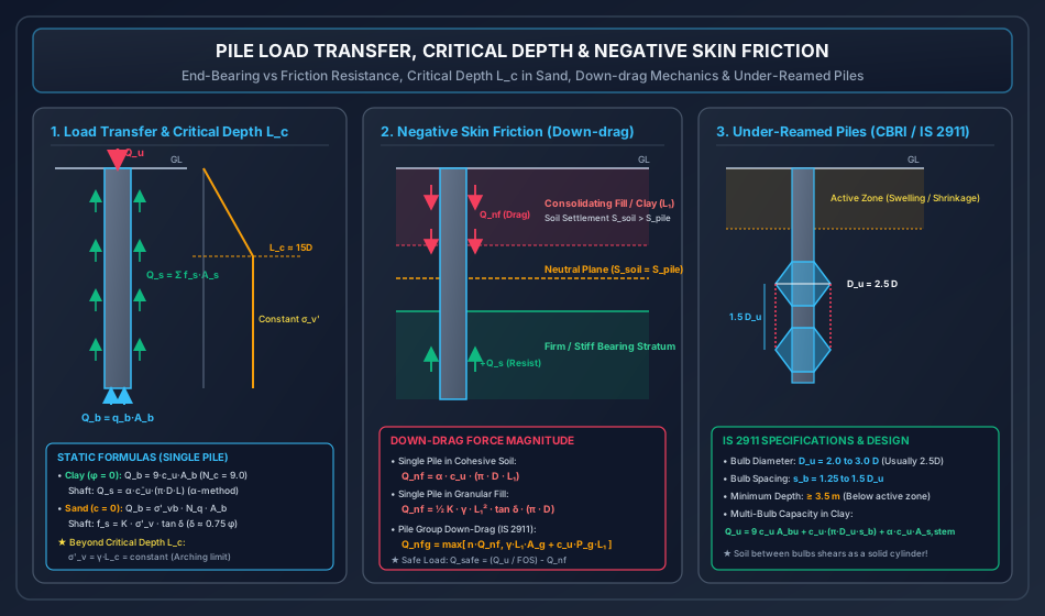
A. Cohesive Soils (Saturated Clays, ):
For deep foundations embedded in clay under undrained loading:
-
Base Resistance ():
where:
- is the undrained shear strength of clay at the pile base.
- is the cross-sectional area of the base.
- Skempton's Invariant for Deep Foundations: For embedment depth ratio , the bearing capacity factor reaches a constant maximum:
-
Shaft Resistance ( via Total Stress -Method, IS 2911):
where:
- is the empirical adhesion factor (), accounting for remolding, smear, and pile-soil interface reduction.
- For soft, normally consolidated clays (): .
- For stiff, overconsolidated clays (): .
B. Cohesionless Soils (Sands, ):
In sands, resistance is governed by effective overburden pressure and frictional shearing:
-
Base Resistance ():
where:
- is the effective vertical overburden stress at the pile tip.
- is the deep foundation bearing capacity factor (Berezantsev, Meyerhof, or IS 2911).
-
Shaft Resistance ():
where:
- is the earth pressure coefficient ( for driven displacement piles; for bored piles).
- is the interface angle of skin friction between pile material and sand ( for concrete/steel; for smooth steel; for rough timber/cast-in-place concrete).
The Critical Depth Phenomenon () in Sands:
Theoretical effective overburden stress increases linearly with depth indefinitely. However, extensive in-situ instrumented pile load tests (Meyerhof 1976, Vesic 1977) demonstrated that beyond a certain critical depth (), vertical effective stress stops increasing due to soil arching:
- For depths : ; both unit shaft friction and unit base resistance increase linearly.
- For depths : Effective vertical stress remains constant at its limiting value:
Design Warning: Neglecting critical depth leads to massive, unsafe overestimation of pile capacities in deep driven foundations!
4. Dynamic Pile Driving Formulas
For driven displacement piles in granular soils, dynamic formulas estimate ultimate capacity from the hammer energy delivered and the resulting permanent pile set (penetration per blow).
1. Engineering News Record (ENR) Formula:
Derived from the conservation of energy principle ():
where:
- is the weight of the hammer (kN or kg).
- is the height of free fall of the hammer (cm).
- is the permanent penetration (set) per blow, averaged over the last 10 blows (cm).
- is an empirical factor accounting for temporary elastic compression losses:
- Drop Hammer: ().
- Single-Acting Steam / Diesel Hammer: ().
- is the prescribed factor of safety.
2. Hiley Formula:
A more rigorous dynamic equation incorporating hammer efficiency , coefficient of restitution , and measured elastic compressions:
where:
- is the blow efficiency (where is pile weight and is restitution coefficient).
- are the temporary elastic compressions of the pile dolly/packing, the pile shaft, and the subsoil, respectively.
5. Pile Group Action & Failure Modes in Clays
Foundations rarely utilize isolated single piles. Piles are clustered in groups () interconnected at the top by a rigid reinforced concrete pile cap.
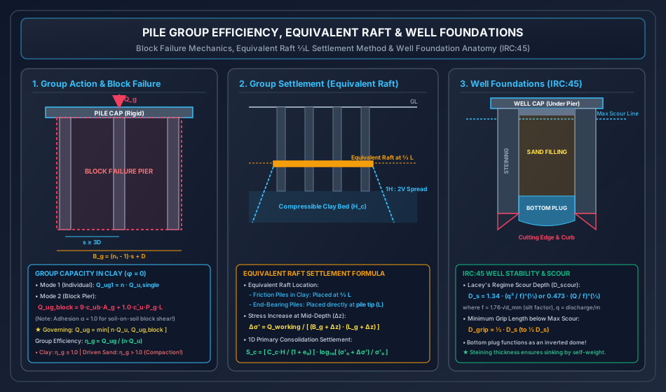
Minimum Center-to-Center Pile Spacing ():
- Friction Piles: (prevents overlapping shear stress zones).
- End-Bearing Piles: .
- Compaction Piles in Loose Sand: .
Failure Modes in Cohesive Soil (Clays):
In a pile group embedded in clay, failure can occur via two competing mechanisms:
Mode 1: Individual Pile Failure:
Each pile shears the surrounding clay independently:
where is the total number of piles in the group.
Mode 2: Block (Pier) Failure:
The piles and the trapped inter-pile soil mass act as a single, monolithic, rigid deep rectangular block of dimensions:
- Base Area of Block: .
- Perimeter of Block: .
- Ultimate Capacity of Equivalent Block Pier:
Critical Distinction: For block failure, shear takes place along soil-on-soil planes along the outer perimeter . Therefore, the adhesion factor is identically (full cohesion ), whereas for individual piles, (soil-on-pile interface).
Governing Ultimate Group Capacity:
6. Pile Group Efficiency Formulations
Group efficiency evaluates the ratio of group capacity to the sum of individual capacities:
Converse-Labarre Empirical Formula (Friction Piles):
where:
- in degrees.
- and are the number of rows and columns.
Group Efficiency Contrast: Clays vs. Sands:
- Piles in Cohesive Clays ():
- Stress fields around adjacent piles overlap, inducing higher shear stresses in the inter-pile clay.
- Group efficiency is always (typically ).
- Driven Displacement Piles in Cohesionless Sands ():
- Driving piles into sand compacts and densifies the inter-pile soil mass, dramatically increasing , , and lateral pressure .
- Group efficiency is strictly (frequently )!
- In conservative structural design, is taken as .
7. Settlement of Pile Groups: The Equivalent Raft Method
Settlement of a pile group in compressible clay is calculated by replacing the pile group with an Equivalent Raft Foundation:
1. Equivalent Raft Placement Depth:
- Friction (Floating) Pile Group in Clay: The equivalent raft of dimensions is positioned at a depth of below the pile cap (where is the pile length).
- End-Bearing Pile Group: The equivalent raft is placed directly at the pile tip level ().
2. Stress Dispersion ():
The working load spreads downward from the equivalent raft at a slope of (or to vertical).
At a depth below the equivalent raft, the footprint expands to:
The net vertical stress increment at mid-depth of a compressible clay layer is:
3. Primary Consolidation Settlement ():
Using Terzaghi's 1D consolidation formulation:
where is the initial effective overburden stress at the mid-depth of the compressible stratum.
8. Negative Skin Friction (Down-Drag) Mechanics
Negative skin friction is a downward shear drag exerted on the pile shaft by surrounding soil that settles more than the pile itself. Instead of supporting the pile, down-drag acts as an additional gravity load!
Physical Triggers:
- Consolidation of a recently placed loose or soft fill layer deposited over compressible subsoil.
- Surcharge loading placed on ground adjacent to the pile foundation.
- Lowering of the regional groundwater table, increasing effective overburden stress () and triggering subsoil consolidation.
The Neutral Plane:
The depth at which the settlement of the soil exactly equals the settlement of the pile is the neutral plane:
- Above the neutral plane: Soil settles more than the pile Friction acts downward (Negative Skin Friction ).
- Below the neutral plane: Pile moves downward relative to soil Friction acts upward (Positive Skin Resistance ).
Mathematical Formulations for Negative Skin Friction ():
-
Single Pile in Cohesive Soil:
where is the thickness of the consolidating clay/fill layer above the neutral plane.
-
Single Pile in Granular / Cohesionless Fill:
-
Pile Group Down-Drag (IS 2911): The down-drag on a group is the greater of:
- Sum of individual pile drags:
- Monolithic block down-drag: Weight of fill within group footprint + perimeter shear:
Allowable Pile Capacity with Down-Drag:
9. Under-Reamed Piles in Expansive Black Cotton Soils (IS 2911 Part 3)
Developed in India by the Central Building Research Institute (CBRI, Roorkee), under-reamed piles provide the standard foundation solution for structures built on deep expansive clays (Black Cotton soils) that undergo high seasonal swelling and shrinkage.
Geometric Specifications (IS 2911 Part 3:1980):
- Stem Diameter (): Typically to .
- Bulb Diameter (): Enlarged base bulb created using a mechanical under-reaming tool:
- Spacing Between Multiple Bulbs ():
- Minimum Embedment Depth (): Piles must extend to at least below ground level to anchor firmly into stable, non-expansive clay below the active moisture variation depth ().
Capacity Formulation of Multi-Under-Reamed Piles in Clay:
For a multi-bulb under-reamed pile in clay ():
- Base bearing acts on the lowest bulb: .
- Soil between adjacent bulbs shears as a solid cylinder of diameter :
- Shaft friction along the upper stem above the top bulb:
10. Well Foundations & Caissons for Bridges (IRC:45)
Well foundations (open caissons) are deep, massive hollow substructures sunk into alluvial riverbeds to support heavy bridge piers and abutments.
Anatomy & Structural Elements (IRC:45-1972):
- Cutting Edge: Heavy structural steel angle or wedge mounted at the bottom to cut through soil strata during sinking.
- Well Curb: Triangular reinforced concrete section supporting the steining and facilitating soil excavation toward the central dredging well.
- Steining: Thick annular concrete or masonry wall providing the massive dead weight required to overcome skin friction and sink the well.
- Dredge Hole: Central shaft through which soil is excavated underwater using grab buckets.
- Bottom Plug: Massive mass concrete plug placed underwater via tremie pipe upon reaching final founding depth, acting as an inverted dome transferring pier loads into the bearing stratum.
- Sand Filling: Granular fill placed above the bottom plug to add stabilizing dead weight and reduce moments.
- Top Plug: Concrete seal placed over sand filling to support the well cap.
- Well Cap: Reinforced concrete slab connecting the well steining to the bridge pier.
Lacey's Regime Scour Depth ():
Foundations in alluvial rivers must penetrate safely below the maximum potential riverbed scour:
where:
- is the design discharge per unit width ().
- is Lacey's Silt Factor ( is mean particle diameter).
Minimum Grip Length ():
To ensure lateral stability against horizontal flood and seismic drag forces, the well must be embedded below the maximum scour level by a minimum grip length:
11. Solved Numerical Problems
Problem 1: Static Capacity of Single Pile in Stratified Clay & Sand with Critical Depth
Statement: A precast driven concrete pile of circular cross-section () and total embedment length is installed in a stratified subsoil deposit:
- Layer 1 (Depth to ): Soft normally consolidated clay with .
- Layer 2 (Depth to ): Medium stiff clay with .
- Layer 3 (Depth to ): Dense sand into which the pile penetrates and terminates. Soil properties: , bearing capacity factor , earth pressure coefficient , interface friction (). Critical depth in sand is . Groundwater table is deep.
(a) Calculate the ultimate shaft resistance developed in Layer 1 () and Layer 2 ().
(b) Calculate the ultimate shaft resistance developed in Layer 3 sand () and the ultimate base resistance at the pile tip ().
(c) Determine the total ultimate bearing capacity and the allowable design load using a factor of safety .
Solution:
Given: .
- Perimeter: .
- Base area: .
(a) Shaft Resistance in Cohesive Layers 1 and 2:
- Layer 1 ():
- Layer 2 ():
(b) Shaft and Base Resistance in Layer 3 Sand:
- Overburden stress at top of sand layer ():
- Check critical depth in sand: The penetration into sand is . Hence, vertical stress continues to increase linearly to the pile tip!
- Vertical stress at pile tip ():
- Average vertical stress along pile shaft in sand:
- Unit skin friction in sand:
- Shaft resistance in sand:
- Ultimate base resistance at pile tip:
(c) Total Ultimate and Safe Capacities:
- Total ultimate bearing capacity:
- Allowable design load ():
Problem 2: Pile Group Capacity, Efficiency, and Settlement by Equivalent Raft
Statement: A building foundation requires a square pile group ( piles) of circular concrete piles (, length ). Piles are embedded in a deep homogeneous saturated clay stratum:
- Undrained shear strength:
- Unit weight:
- Pile spacing: ()
- Adhesion factor for individual pile:
(a) Determine the ultimate load capacity of a single isolated pile ().
(b) Determine the group capacity assuming individual pile failure ().
(c) Determine the group capacity assuming block failure (). Establish the governing ultimate group capacity and group efficiency .
(d) The pile group transfers a working design load to an equivalent raft placed at depth. An underlying compressible clay stratum of thickness is located between depths and (mid-depth at ) with initial void ratio and compression index . Assuming a stress dispersion, compute the 1D primary consolidation settlement of this clay layer.
Solution:
Given: .
(a) Single Pile Ultimate Capacity:
- Perimeter: .
- Base Area: .
- Base Resistance:
- Shaft Resistance:
- Single Pile Capacity:
(b) Group Capacity based on Individual Failure:
(c) Group Capacity based on Block Failure:
- Dimensions of block:
- Base Area of block: .
- Perimeter of block: .
- Block Base Capacity:
- Block Shaft Capacity (soil-on-soil block shear ):
- Total Block Capacity:
Governing Group Capacity & Efficiency: Since :
(d) Equivalent Raft Settlement Analysis:
- Depth of Equivalent Raft:
- Compressible clay layer is between and ; mid-depth is .
- Depth interval from equivalent raft to mid-depth of clay:
- Using spread, dimensions at depth expand by :
- Vertical stress increment at mid-depth:
- Initial effective overburden stress at mid-depth ():
- Primary consolidation settlement:
Problem 3: Negative Skin Friction (Down-drag) and Net Allowable Load
Statement: A driven tubular steel pipe pile (, total length ) penetrates through:
- Layer 1 (Depth to ): Recently placed hydraulic clay fill undergoing consolidation ().
- Layer 2 (Depth to ): Highly compressible soft clay undergoing consolidation under fill surcharge ().
- Layer 3 (Depth to ): Competent dense gravel-bearing stratum () into which the pile is embedded. Geotechnical parameters in bearing stratum: unit base resistance , unit shaft friction .
The neutral plane is located precisely at the interface between Layer 2 and Layer 3 ().
(a) Determine the total down-drag force (negative skin friction ) acting on the pile shaft.
(b) Calculate the ultimate base capacity () and positive shaft capacity () developed in the bearing stratum.
(c) Determine the safe allowable column load using applied to positive resistance:
Solution:
Given: .
- Perimeter: .
- Base Area: .
(a) Negative Skin Friction ():
- Down-drag in Layer 1 (Fill, ):
- Down-drag in Layer 2 (Soft consolidating clay, ):
- Total Negative Skin Friction:
(b) Positive Capacity in Bearing Stratum (Layer 3, ):
- Ultimate Base Capacity:
- Ultimate Positive Shaft Resistance:
- Total Ultimate Positive Capacity:
(c) Net Safe Allowable Column Load:
Engineering Assessment: Down-drag reduces the net safe column load from to ( capacity loss). To eliminate negative skin friction, the upper pipe section can be coated with bitumen slip-layers or surrounded by a loose outer casing sleeve!
12. Comparative Engineering Analysis Across Syllabi
┌────────────────────────────────────────────────────────────────────────────────────────────────────────┐
│                        SYLLABUS EMPHASIS & EXAMINATION FOCUS MATRIX                            │
├─────────────┬─────────────────────────────────────────────────┬────────────────────────────────────────┤
│ Examination │ High-Yield Core Focus Areas                     │ Typical Question Typology              │
├─────────────┼─────────────────────────────────────────────────┼────────────────────────────────────────┤
│ GATE CE     │ • Static capacity in sand with critical depth   │ 2-mark NAT numericals on block failure │
│             │ • Negative skin friction on single & group      │ vs individual failure; equivalent raft │
│             │ • Group efficiency in clay vs sand              │ ⅔L settlement; under-reamed bulb rules │
├─────────────┼─────────────────────────────────────────────────┼────────────────────────────────────────┤
│ UPSC ESE    │ • Analytical derivations of dynamic formulas    │ 15-20 mark conventional questions:     │
│             │ • Pile group settlement equivalent raft proofs  │ Converse-Labarre derivation; Lacey     │
│             │ • Well foundation forces, tilts, and scour      │ scour depth & grip length calculations │
├─────────────┼─────────────────────────────────────────────────┼────────────────────────────────────────┤
│ SSC JE &    │ • ENR formula C = 2.5 cm (drop), 0.25 cm (steam)│ Rapid MCQs on under-reamed bulb size   │
│ RRB JE      │ • Minimum pile spacing 2.5D to 3.0D             │ Du = 2.5D; minimum depth 3.5 m;        │
│             │ • Skempton N_c = 9.0 for deep piles             │ cutting edge and bottom plug functions │
├─────────────┼─────────────────────────────────────────────────┼────────────────────────────────────────┤
│ State AE/JE │ • Lacey scour depth D_s = 1.34 (q²/f)^(⅓)       │ Direct formula evaluations; negative   │
│             │ • Block perimeter shear adhesion α = 1.0        │ skin friction reduction of safe load   │
└─────────────┴─────────────────────────────────────────────────┴────────────────────────────────────────┘
13. Common Misconceptions & Examination Pitfalls
-
Adhesion Factor in Group Block Failure:
- Trap: Applying the individual pile adhesion factor () to the perimeter of the block failure.
- Reality: Block failure shears soil against soil along the outer perimeter . Soil-on-soil shear always has (full cohesion ).
-
Group Efficiency in Sand vs. Clay:
- Trap: Assuming pile group efficiency is always less than .
- Reality: In clays, due to stress overlap. In driven displacement piles in loose-medium sand, compaction increases relative density, making (frequently )!
-
Equivalent Raft Depth in End-Bearing vs. Friction Piles:
- Trap: Placing the equivalent raft at for all pile groups.
- Reality: The rule applies strictly to friction piles in clay. For end-bearing piles terminating on a hard layer, the equivalent raft is placed directly at the pile tip ().
-
Negative Skin Friction Sign:
- Trap: Treating negative skin friction as a component of resisting capacity.
- Reality: Negative skin friction acts downward as a driving gravitational load. It must be added to the working load or subtracted from allowable capacity ().
-
Critical Depth in Granular Soil:
- Trap: Continuing to increase to 30 or 40 meters depth.
- Reality: Due to soil arching, effective vertical stress becomes constant beyond (loose) to (dense).