Shear Strength of Soil, Mohr-Coulomb Criterion, Direct Shear, Triaxial (UU/CU/CD), UCC, Vane Shear & Pore Pressure Parameters (A, B)
In this chapter (8 topics)
On this page
- 1. Module Overview & Learning Objectives
- Core Exam Focus Areas
- 2. Nature of Shear Strength & Mohr-Coulomb Failure Criterion
- 2.1 Coulomb's Shear Law (1776)
- 2.2 Terzaghi's Effective Stress Modification (1936)
- 3. Mathematical Derivations & Analytical Formulations
- 3.1 State of Stress on an Arbitrary Plane
- 3.2 Orientation of the Theoretical Failure Plane (θcr)
- 3.3 Principal Stresses at Failure
- 4. Visual Master Diagram: Mohr-Coulomb Criterion & Triaxial Stress Paths
- 5. State of Stress & Triaxial Stress Paths (p - q Space)
- 5.1 Stress Path Coordinates (MIT System)
- 5.2 The Modified Failure Envelope (Kf Line)
- 6. Visual Master Diagram: Laboratory Apparatus & Skempton's Parameters
- 7. Laboratory Shear Strength Testing Methods
- 8. Triaxial Drainage Regimes: UU, CU, and CD Tests
- 8.1 Unconsolidated Undrained (UU) Test ("Quick Test")
- 8.2 Consolidated Undrained (CU) Test
- 8.3 Consolidated Drained (CD) Test ("Slow Test")
- 9. UCC Test & Vane Shear Test Analytical Formulations
- 9.1 Unconfined Compression (UCC) Test
- 9.2 Vane Shear Test Formulation
- 10. Skempton's Pore Pressure Parameters (A and B)
- 10.1 Skempton's Parameter B (Hydrostatic Stage)
- 10.2 Skempton's Parameter A (Shearing Stage)
- 11. Solved Numerical Problems (Step-by-Step, Pre-Calculated)
- Problem 1: Triaxial CU Test Data Reduction (Total vs. Effective Shear Parameters) (GATE CE / UPSC ESE)
- Problem 2: Vane Shear Test & Soil Sensitivity (SSC JE / State AE)
- Problem 3: Skempton's Pore Pressure Parameters in Triaxial Testing (UPSC ESE / GATE CE)
- 12. Comparative Engineering Analysis & Multi-Exam Question Patterns
- 13. Common Misconceptions, Pitfalls & Pro-Tips
- Critical Traps to Avoid in Competitive Exams
- 14. Key Reference Formulas & Summary Table
1. Module Overview & Learning Objectives
Shear strength is the internal resistance per unit area that a soil mass can mobilize to withstand failure and sliding along any internal surface. Virtually all fundamental geotechnical engineering problems—including:
- Ultimate bearing capacity and safety against foundation punch-through failure,
- Lateral earth pressures exerted on retaining walls, basement basements, and sheet-pile bulkheads,
- Slope stability of highway embankments, earth dams, deep railway cuts, and open-pit mines, are governed directly by the shear strength of the soil. Soil rarely fails in direct compressive crushing (like concrete or rock); failure almost universally occurs in shear along localized slip surfaces.
+----------------------------------------------------------------------------------------------------+
|                                  THE SHEAR STRENGTH MATRIX OF SOIL                                 |
+----------------------+----------------------+------------------------------------------------------+
| STRESS FORMULATION   | GOVERNING EQUATION   | PHYSICAL SIGNIFICANCE & RELEVANT CONDITIONS          |
+----------------------+----------------------+------------------------------------------------------+
| Total Stress         | tau_f = c + sigma*   | Applied in short-term undrained problems (UU tests)  |
| Analysis (TSA)       | tan(phi)             | where excess pore pressure cannot dissipate.         |
+----------------------+----------------------+------------------------------------------------------+
| Effective Stress     | tau_f = c' + sigma'* | True fundamental law of physical shear resistance.   |
| Analysis (ESA)       | tan(phi')            | Controls all long-term stability and drained shearing|
+----------------------+----------------------+------------------------------------------------------+
| Undrained Shear      | tau_f = c_u          | Saturated clay under fast loading (phi_u = 0 concept)|
| Strength (phi_u = 0) | (q_u = 2 c_u)        | Cell pressure sigma_3 does not alter shear strength. |
+----------------------+----------------------+------------------------------------------------------+
Core Exam Focus Areas
- GATE CE: Conversion between Total and Effective Mohr circles (horizontal translation by pore pressure ); Analytical derivation of and failure plane angle ; Skempton's pore pressure equation ; Vane shear torque calculations for one vs. two ends sheared.
- UPSC ESE: Detailed comparison of Direct Shear vs. Triaxial Shear apparatus; Complete mechanics of UU, CU, and CD tests and their field prototype correlations (e.g., sudden drawdown behind dam CU); Derivation of line parameters in MIT space (); Critical state friction angle vs. peak friction angle with dilatancy.
- SSC JE / State AE / RRB JE: Formula memory: for unconfined compression test; Vane shear torque formula ; Direct shear test limitations (predetermined horizontal failure plane, non-uniform stress); Skempton's parameter for fully saturated soil; Failure plane orientation with major principal plane () vs. minor principal plane ().
2. Nature of Shear Strength & Mohr-Coulomb Failure Criterion
Natural soil derives its shear strength from two distinct physical sources:
- Frictional Resistance (): Interlocking between discrete soil grains and sliding friction across mineral contact facets. Frictional resistance is proportional to the normal effective confining stress .
- True Cohesion (): Interparticle electro-chemical bonding and cementation between fine clay platelets, independent of normal stress.
2.1 Coulomb's Shear Law (1776)
Charles-Augustin de Coulomb postulated that the limiting shear stress on any slip plane is a linear function of total normal stress :
Where is apparent cohesion and is the angle of internal friction.
2.2 Terzaghi's Effective Stress Modification (1936)
Because water possesses zero shear strength and cannot carry deviatoric stress, Terzaghi modified Coulomb's law to express shear strength exclusively in terms of effective normal stress ():
Where:
- is the effective cohesion intercept ().
- is the effective angle of internal friction (degrees).
3. Mathematical Derivations & Analytical Formulations
3.1 State of Stress on an Arbitrary Plane
Consider an element of soil subjected to major principal stress and minor principal stress . On an arbitrary plane inclined at an angle to the direction of the major principal plane (the plane carrying ):
                         sigma_1
                         | | | |
                      +-----------+
                      |     /     |
            sigma_3 ->|    / theta|<- sigma_3
                      |   /       |
                      +-----------+
                         ^ ^ ^ ^
                         sigma_1
3.2 Orientation of the Theoretical Failure Plane ()
In Mohr's stress plane (), the failure state occurs when the Mohr stress circle expands until it becomes strictly tangent to the linear Mohr-Coulomb failure envelope . From the geometry of the right-angled triangle formed by the circle center , the origin , and the point of tangency: The angle subtended at the center of the Mohr circle is:
Where:
- is the angle that the critical failure plane makes with the major principal plane (horizontal plane in standard triaxial testing).
- The angle that the failure plane makes with the direction of major principal stress (vertical axis) is:
3.3 Principal Stresses at Failure
From the right-angled triangle connecting circle center and envelope tangency:
Expanding and rearranging:
Using the trigonometric identities:
Substituting yields the classical Principal Stress Failure Formulation:
Important Special Cases:
- Purely Cohesionless Sand ():
- Purely Cohesive Saturated Clay under Undrained Conditions (): Notice that the diameter of the Mohr circle () remains completely constant regardless of cell pressure !
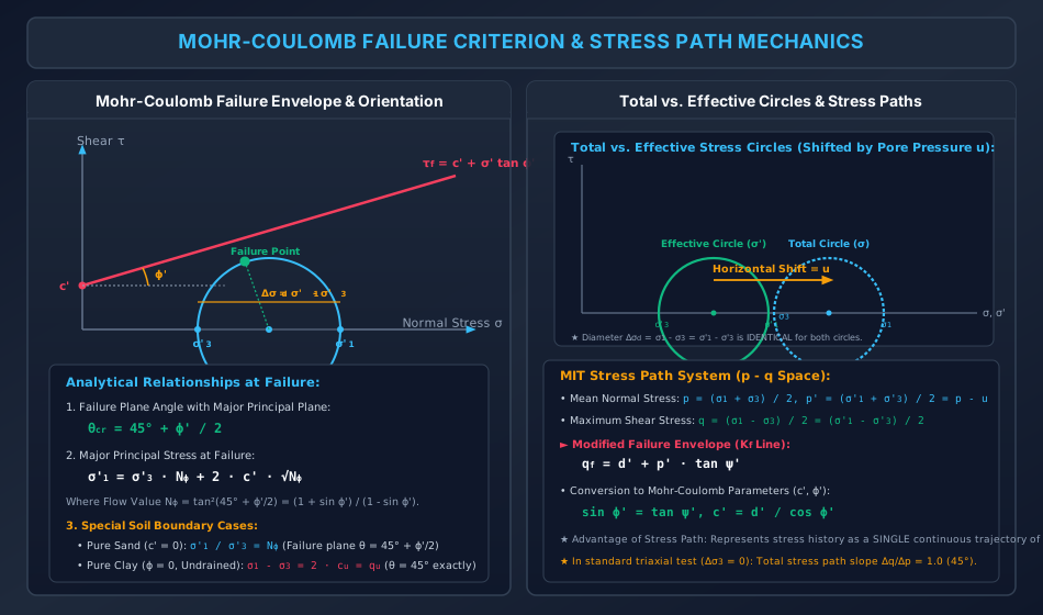
4. Visual Master Diagram: Mohr-Coulomb Criterion & Triaxial Stress Paths
The following architectural diagram illustrates the Mohr-Coulomb failure envelope, the geometry of the failure plane angle (), the relationship between Total and Effective Mohr circles (horizontal translation by pore pressure ), and the MIT stress path system.
5. State of Stress & Triaxial Stress Paths ( Space)
In complex geotechnical problems involving sequential excavation, embankment staging, or cyclic wave loading, plotting multiple overlapping Mohr circles causes severe graphical confusion. To resolve this, T.W. Lambe and the MIT school developed the Stress Path Method, where the complete state of stress on a specimen is represented by a single coordinate point:
5.1 Stress Path Coordinates (MIT System)
5.2 The Modified Failure Envelope ( Line)
The locus of peak stress points defines a straight line termed the line:
The relationship between the stress path parameters () and the standard Mohr-Coulomb parameters () is:
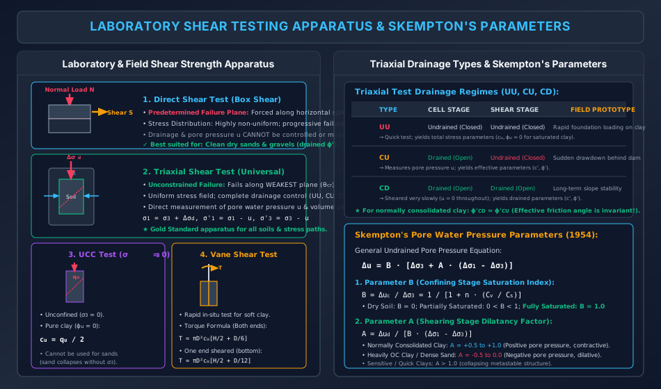
6. Visual Master Diagram: Laboratory Apparatus & Skempton's Parameters
The following architectural diagram illustrates the experimental configurations, failure planes, and stress states of the Direct Shear Test, Triaxial Shear Cell, Unconfined Compression Test (UCC), and Vane Shear Test, along with the Triaxial Drainage Regimes (UU, CU, CD) and Skempton's pore pressure formulation.
7. Laboratory Shear Strength Testing Methods
+----------------------+----------------------+----------------------+-------------------------------+
| TEST METHOD          | PRINCIPAL ADVANTAGES | CRITICAL LIMITATIONS | PRIMARY APPLICATION           |
+----------------------+----------------------+----------------------+-------------------------------+
| 1. Direct Shear Test | Rapid, simple, quick | Predetermined plane; | Drained shear parameters      |
|    (IS 2720 Part 13) | drainage for sands.  | non-uniform stresses;| (c', phi') of clean sands,    |
|                      | Compact box design.  | cannot measure u.    | gravels, and rock joints.     |
+----------------------+----------------------+----------------------+-------------------------------+
| 2. Triaxial Shear    | Universal; drainage  | Elaborate setup;     | Comprehensive analysis of all |
|    Test              | control (UU, CU, CD);| membranes required;  | soils; effective parameters   |
|    (IS 2720 Part 11) | uniform stress; u &  | longer testing time  | (c', phi') & undrained c_u.   |
|                      | volume measurement.  | for drained tests.   | Gold Standard in geotechnical.|
+----------------------+----------------------+----------------------+-------------------------------+
| 3. Unconfined Compr. | Highly rapid; simple | sigma_3 = 0 strictly;| Undrained shear strength c_u  |
|    (UCC) Test        | field testing; no    | only for cohesive    | of intact, saturated, stiff to|
|    (IS 2720 Part 10) | cell pressure needed.| clays (sands fail).  | firm clays.                   |
+----------------------+----------------------+----------------------+-------------------------------+
| 4. Vane Shear Test   | In-situ measurement; | Purely undrained;    | In-situ undrained strength c_u|
|    (IS 2720 Part 30) | no sampling distur-  | assumes isotropic c_u| of very soft sensitive clays, |
|                      | bance; fast torque.  | on cylindrical shear.| marine muds, organic deposits.|
+----------------------+----------------------+----------------------+-------------------------------+
8. Triaxial Drainage Regimes: UU, CU, and CD Tests
A triaxial compression test is conducted in two sequential stages:
- Stage 1 (Cell Pressure Application): The specimen is placed under an all-around hydrostatic cell pressure .
- Stage 2 (Deviator Shearing): An additional axial compressive stress () is applied until shear failure occurs.
8.1 Unconsolidated Undrained (UU) Test ("Quick Test")
- Drainage: Drainage valve remains closed in both stages (cell stage and shear stage).
- Duration: Sheared very rapidly (typically ). No pore water drainage is permitted.
- Parameters: Yields total stress undrained parameters ().
- The Concept: For fully saturated clays (), increasing cell pressure causes an equal increase in pore pressure (), meaning effective confining stress remains completely unchanged. Consequently, the failure deviator stress is identical regardless of cell pressure . The failure envelope is a horizontal line with and .
- Field Prototype: End-of-construction stability of a foundation or embankment placed rapidly over an impervious saturated clay layer before any consolidation can occur.
8.2 Consolidated Undrained (CU) Test
- Drainage: Drainage valve is open during Stage 1 (specimen consolidates fully under until excess ). Drainage valve is closed during Stage 2 (shearing is undrained, but excess pore pressure is measured with an electronic transducer).
- Parameters: Yields total stress parameters () and, via effective stresses (), yields fundamental effective parameters ().
- Field Prototype: Sudden drawdown of water level in a reservoir behind an earth dam; rapid post-consolidation loading on an existing structure.
8.3 Consolidated Drained (CD) Test ("Slow Test")
- Drainage: Drainage valve is open in both stages.
- Duration: Shearing rate is kept exceptionally slow (days to weeks) so that no excess pore water pressure develops ( throughout).
- Parameters: Yields drained parameters ().
- Equivalence: For normally consolidated clays, (effective friction angle is identical to CU effective friction angle).
- Field Prototype: Long-term permanent stability of slopes, railway cuttings, and retaining walls decades after construction.
9. UCC Test & Vane Shear Test Analytical Formulations
9.1 Unconfined Compression (UCC) Test
The UCC test is a special limiting case of the triaxial test where cell pressure is zero:
Where is the unconfined compressive strength. Substituting and into the principal stress failure equation:
9.2 Vane Shear Test Formulation
A four-bladed steel cruciform vane (diameter , height , typically ) is pushed into an undisturbed clay bed and rotated at a constant standard rate (). Shear resistance mobilizes along a cylindrical surface of diameter and height , and across the top and bottom circular ends:
Case 1: Both Ends of Vane Sheared (Vane fully embedded at depth)
Total resisting torque is the sum of cylindrical mantle torque () and two circular end torques ():
Solving for undrained shear strength :
Case 2: Only Bottom End Sheared (Vane top flush with ground/trench surface)
10. Skempton's Pore Pressure Parameters ( and )
A.W. Skempton (1954) formulated the generalized equation predicting the change in pore water pressure in a saturated or unsaturated soil element under arbitrary changes in principal stresses:
10.1 Skempton's Parameter (Hydrostatic Stage)
Parameter governs the pore pressure generated during isotropic confining cell pressure increase ():
Where is porosity, is compressibility of pore fluid, and is compressibility of soil skeleton.
- Dry Soil (Air in pores, ): .
- Partially Saturated Soil: .
- Fully Saturated Soil (, water compressibility ): .
10.2 Skempton's Parameter (Shearing Stage)
Parameter governs the pore pressure generated during deviator stress application ():
Parameter is an intrinsic indicator of soil dilatancy and volumetric tendency under shear:
+------------------------------------+------------------------------------+
| SOIL TYPE & FABRIC                 | SKEMPTON'S A VALUE AT FAILURE      |
+------------------------------------+------------------------------------+
| Heavily Overconsolidated Clay (OC) | -0.5 to 0.0 (Strong dilation)      |
| Dense Cohesionless Sand            | -0.3 to 0.0 (Dilatant)             |
| Lightly Overconsolidated Clay      | 0.0 to 0.5                         |
| Normally Consolidated Clay (NC)    | +0.5 to +1.0 (Contractive)         |
| Loose Cohesionless Sand            | +0.5 to +1.0 (Contractive)         |
| Sensitive / Quick Marine Clays     | +1.0 to +3.0 (Collapsing fabric)   |
+------------------------------------+------------------------------------+
11. Solved Numerical Problems (Step-by-Step, Pre-Calculated)
Problem 1: Triaxial CU Test Data Reduction (Total vs. Effective Shear Parameters) (GATE CE / UPSC ESE)
Two identical cylindrical specimens of a saturated cohesive soil were tested in Consolidated Undrained (CU) triaxial compression with pore pressure measurement. The test results at failure are:
- Specimen 1:
- Cell pressure:
- Deviator stress at failure:
- Pore water pressure at failure:
- Specimen 2:
- Cell pressure:
- Deviator stress at failure:
- Pore water pressure at failure:
Determine:
- The total stress shear parameters ().
- The effective stress shear parameters ().
- The inclination of the failure plane () with respect to the horizontal for Specimen 1.
Solution:
Step 1: Compute total and effective principal stresses at failure
-
Specimen 1:
-
Specimen 2:
Step 2: Total Stress Shear Parameters () Using :
Step 3: Effective Stress Shear Parameters () Using :
Step 4: Orientation of the Failure Plane ()
Problem 2: Vane Shear Test & Soil Sensitivity (SSC JE / State AE)
A field vane shear test was conducted in a deposit of soft marine clay using a standard four-bladed vane of diameter and height . The torque required to shear the soil with both top and bottom circular ends embedded was . The vane was then rotated rapidly through 10 complete revolutions to thoroughly remold the soil. The torque required to shear the remolded clay was .
Determine:
- The undisturbed undrained shear strength ().
- The remolded undrained shear strength ().
- The sensitivity () of the clay deposit and classify its structural fabric.
- The estimated unconfined compressive strength () of undisturbed clay.
Solution:
Step 1: Compute geometric vane denominator Both ends of the vane are sheared:
Step 2: Undrained shear strengths
- Undisturbed:
- Remolded:
Step 3: Sensitivity Classification
- Classification per Skempton: Since , the clay is categorized as Sensitive Clay.
Step 4: Unconfined Compressive Strength ()
Problem 3: Skempton's Pore Pressure Parameters in Triaxial Testing (UPSC ESE / GATE CE)
An undisturbed specimen of saturated clay was subjected to a Consolidated Undrained triaxial test with an initial back pressure of .
- During the cell pressure increase stage, the all-around chamber pressure was raised from to under undrained conditions (). The pore water pressure transducer registered an increase of . Calculate Skempton's parameter and verify the degree of saturation.
- During the subsequent shearing stage, the axial deviator stress was increased from to at failure (). The pore water pressure increased by an additional . Calculate Skempton's parameter at failure.
- Compute the total pore water pressure () inside the specimen at the moment of failure.
Solution:
Step 1: Skempton's Parameter
- Since , the specimen is fully saturated without entrapped air.
Step 2: Skempton's Parameter From Skempton's undrained pore pressure equation during shearing ():
- Since , the soil demonstrates positive pore pressure generation (contractive tendency typical of lightly overconsolidated or normally consolidated clay).
Step 3: Total Pore Water Pressure at Failure
12. Comparative Engineering Analysis & Multi-Exam Question Patterns
+------------------------------------+-------------------------------------------------------------------------------------------------------------------+
| EXAM LEVEL                         | HIGHEST YIELD TOPICS & TYPICAL QUESTION PATTERNS                                                                 |
+------------------------------------+-------------------------------------------------------------------------------------------------------------------+
| GATE CE                            | - CU triaxial data reduction: extraction of $c'$ and $\phi'$ from two failure stress points.                      |
|                                    | - Skempton's pore pressure equation and parameter $A$ computation at failure.                                     |
|                                    | - Critical failure plane orientation ($\theta = 45^\circ + \phi/2$) with major vs minor principal axes.            |
|                                    | - Vane shear test torque reduction (two ends vs one end sheared).                                                |
+------------------------------------+-------------------------------------------------------------------------------------------------------------------+
| UPSC ESE                           | - Derivation of $\sigma_1 = \sigma_3 N_\phi + 2 c \sqrt{N_\phi}$ from Mohr circle tangency.                     |
|                                    | - Conversion from MIT $p-q$ space to Mohr-Coulomb parameters ($\sin\phi' = \tan\psi', c' = d'/\cos\phi'$).        |
|                                    | - Complete operational contrast between UU, CU, and CD tests and their field prototype matches.                  |
|                                    | - Dilatancy in dense sands: peak vs critical state friction angles ($\phi_{\text{peak}}' = \phi_{cv}' + \psi$).   |
+------------------------------------+-------------------------------------------------------------------------------------------------------------------+
| SSC JE / RRB JE                    | - Direct shear test limitations (predetermined plane, cannot measure pore pressure).                             |
|                                    | - UCC test formula for pure clay: $c_u = q_u / 2$.                                                                |
|                                    | - Failure plane angle for pure clay under undrained condition: $\theta = 45^\circ$ exactly.                       |
|                                    | - Parameter $B$ value for saturated soil ($B = 1.0$).                                                             |
+------------------------------------+-------------------------------------------------------------------------------------------------------------------+
| State AE / JE                      | - Vane shear torque formula $T = \pi D^2 c_u (H/2 + D/6)$.                                                       |
|                                    | - $\phi_u = 0$ concept in UU tests on saturated clays.                                                           |
|                                    | - Sensitivity definition and ranges ($S_t = c_{u,\text{undist}} / c_{u,\text{remold}}$).                          |
+------------------------------------+-------------------------------------------------------------------------------------------------------------------+
13. Common Misconceptions, Pitfalls & Pro-Tips
Critical Traps to Avoid in Competitive Exams
- Failure Plane Angle Reference Trap:
- With the major principal plane (horizontal in triaxial): .
- With the direction of major principal stress (vertical axis): .
- Confusing these two angles is the single most common error in multiple-choice questions!
- Pore Pressure Shift of Mohr Circles: In an undrained test with positive pore pressure , the effective Mohr circle is shifted to the left by distance . However, its diameter remains exactly equal to the total circle diameter because .
- UCC Applicability Trap: The unconfined compression test () can only be performed on cohesive clays. It can never be performed on clean sands or gravels because cohesionless grains cannot stand unsupported under zero confining pressure.
- Vane Shear Ends Trap:
- Both ends sheared: .
- One end sheared: .
- Always verify whether the question specifies the vane is fully embedded or has its top flush at the ground surface!
- Skempton's Parameter Sign: While parameter is always positive (), parameter can be negative (down to ) for heavily overconsolidated clays and dense sands that expand (dilate) during shear!
14. Key Reference Formulas & Summary Table
+-------------------------------------------------------+-------------------------------------------------------------+
| PARAMETER / FORMULA                                   | MATHEMATICAL EXPRESSION                                     |
+-------------------------------------------------------+-------------------------------------------------------------+
| Mohr-Coulomb Effective Failure Law                    | tau_f = c' + sigma' * tan(phi')                             |
+-------------------------------------------------------+-------------------------------------------------------------+
| Failure Plane Angle (with Major Principal Plane)      | theta_cr = 45 deg + phi' / 2                                |
+-------------------------------------------------------+-------------------------------------------------------------+
| Flow Value (N_phi)                                    | N_phi = tan^2(45 deg + phi'/2) = (1 + sin phi')/(1 - sin phi') |
+-------------------------------------------------------+-------------------------------------------------------------+
| Principal Stresses at Failure                         | sigma_1' = sigma_3' * N_phi + 2 * c' * sqrt(N_phi)          |
+-------------------------------------------------------+-------------------------------------------------------------+
| Cohesionless Sand Relation                            | sigma_1' / sigma_3' = N_phi                                 |
+-------------------------------------------------------+-------------------------------------------------------------+
| Pure Saturated Clay (phi_u = 0, Undrained)            | sigma_1 - sigma_3 = 2 * c_u = q_u  (theta = 45 deg)         |
+-------------------------------------------------------+-------------------------------------------------------------+
| UCC Undrained Cohesion                                | c_u = q_u / 2                                               |
+-------------------------------------------------------+-------------------------------------------------------------+
| Vane Shear Test (Both Ends Sheared)                   | c_u = T / [pi * D^2 * (H/2 + D/6)]                          |
+-------------------------------------------------------+-------------------------------------------------------------+
| Vane Shear Test (One End Sheared)                     | c_u = T / [pi * D^2 * (H/2 + D/12)]                         |
+-------------------------------------------------------+-------------------------------------------------------------+
| Skempton's Generalized Pore Pressure Equation         | Delta_u = B * [Delta_sigma_3 + A * (Delta_sigma_1 - Delta_sigma_3)] |
+-------------------------------------------------------+-------------------------------------------------------------+
| Skempton's Parameter B                                | B = Delta_u_c / Delta_sigma_3  (B = 1.0 for S = 100%)       |
+-------------------------------------------------------+-------------------------------------------------------------+
| Skempton's Parameter A                                | A = Delta_u_d / [B * (Delta_sigma_1 - Delta_sigma_3)]       |
+-------------------------------------------------------+-------------------------------------------------------------+
| MIT Stress Path Parameters                            | p = (sigma_1 + sigma_3)/2,  q = (sigma_1 - sigma_3)/2       |
+-------------------------------------------------------+-------------------------------------------------------------+
| Conversion to Mohr-Coulomb Parameters                 | sin(phi') = tan(psi'),  c' = d' / cos(phi')                 |
+-------------------------------------------------------+-------------------------------------------------------------+
Authored with mathematical rigor, IS code precision (IS 2720 Parts 10, 11, 13, 30), and multi-exam alignment for the Civil Engineering Academic Knowledge Repository.