Energy-Depth Relationships, Critical Flow Dynamics, Channel Transitions & Choking Phenomena
In this chapter (4 topics)
On this page
- 1. Module Overview & Pedagogical Scope
- 2. Official Examination Syllabus Mapping
- 3. Fundamental Physical Principles & Governing Assumptions
- 3.1 Total Energy Head vs Specific Energy Head
- 3.2 The Specific Energy Curve (E--y Diagram)
- 4. Mathematical Derivations & Rigorous Proofs
- Proof 1: General Criterion for Critical Flow in Channels of Arbitrary Cross-Section
- Proof 2: Critical Parameters for Rectangular Channels
- Proof 3: Critical Parameters for Triangular Channels
- Proof 4: Channel Transitions — Bed Hump (Δ z) and Choking Mechanics
- Proof 5: Channel Transitions — Width Contraction (Δ B) and Choking Mechanics
- Proof 6: Specific Force & Momentum Function
- 5. Technical Diagrams & Interactive Architectural Schematics
- Diagram 1: Specific Energy & Specific Force Function Dynamics
- Diagram 2: Channel Transitions, Bed Humps & Choking Mechanics
- 6. Comparative Engineering Analysis & Parameter Regimes
- Table 6.1: Critical Depth and Minimum Specific Energy Formulas by Section Shape
- Table 6.2: Alternate Depths vs Conjugate (Sequent) Depths
- 7. Worked Numerical Examples (Pre-Calculated & Verified)
- Problem 1: Critical Depth, Froude Number & Alternate Depths
- Problem 2: Bed Hump Transition & Choking Calculations
- Problem 3: Width Contraction & Triangular Critical Flow
- 8. High-Yield Examination Traps & Ambiguities
- Trap 1: Subcritical vs Supercritical Water Surface Response to a Bed Hump
- Trap 2: Minimum Specific Energy Multipliers (1.5 yc vs 1.25 yc)
- Trap 3: Confusing Alternate Depths with Sequent Depths
- Trap 4: Choking Heading-Up Calculations
- 9. Real-World Engineering Applications & Case Studies
- 9.1 Broad-Crested Weirs & Venturi Flumes as Flow Meters
- 9.2 Culvert Inlet Control & Roadway Overtopping
- 10. Cross-Disciplinary & Downstream Dependencies
- 11. Summary Formula Cheat Sheet & Memory Anchors
- 12. Comprehensive References & Standard Codes
1. Module Overview & Pedagogical Scope
The concept of Specific Energy, first introduced by Boris Bakhmeteff in 1912, represents one of the most fundamental principles in open channel hydraulics. Specific energy () is defined as the total mechanical energy per unit weight of fluid referenced to the channel bed at that cross-section as the datum, rather than an arbitrary horizontal datum:
Unlike pressurized closed pipes, where the pipe geometry fixes the flow area, the free surface in an open channel allows the flow depth to dynamically adjust in response to changes in bed elevation, channel width, discharge, and channel obstructions. This gives rise to:
- Alternate Depths: For a given discharge and specific energy above the minimum, two distinct equilibrium depths of flow exist: a subcritical tranquil flow and a supercritical shooting flow.
- Critical Flow: The unique physical state where specific energy is an absolute minimum for a given discharge (), corresponding to a Froude number of unity ().
- Channel Transitions & Choking: When channel geometry contracts or the bed rises over a hump beyond critical mathematical limits ( or ), the channel cannot convey the incoming discharge under the available upstream specific energy. The flow "chokes", causing an upstream backwater wave that elevates the upstream water surface (heading up).
- Specific Force (Momentum Function): The governing momentum parameter that remains conserved across rapidly varied transitions with unknown internal energy dissipation (such as hydraulic jumps).
2. Official Examination Syllabus Mapping
Website note: this mapping is from the author’s notes. It has not been checked against the official notification for each examination; confirm the current syllabus with the examining body.
| Examination Body | Primary Syllabus Line | Recurring Problem Archetypes |
|---|---|---|
| GATE CE | Specific energy, critical depth, channel transitions (humps and contractions), choking phenomenon. | • Analytical proof of and (rect.) / (tri.). • Precise calculation of critical hump height and upstream water rise during choking. • Calculation of minimum throat width without choking in a Venturi flume. |
| UPSC ESE | Fluid Mechanics & Hydraulic Machinery: Specific energy, Froude number, critical flow, transitions, specific force. | • Multi-shape critical depth equations: Trapezoidal channels with iterative Newton-Raphson solutions. • Graphical interpretation of and curves; alternate vs sequent depths. • Supercritical transitions: Proof that supercritical water surface rises over a bed hump. |
| SSC JE / RRB JE | Hydraulics: Specific energy, critical velocity, critical depth in rectangular channels. | • Formulas for critical velocity () and critical depth (). • Behavior of subcritical vs supercritical flow over a hump (surface drop vs rise). |
| State AE / JE | Water Resources & Irrigation Engineering: Flow measurement and open channel transitions. | • Parshall flume and broad-crested weir design using critical flow dynamics. • Specific force and thrust on sluice gates. |
3. Fundamental Physical Principles & Governing Assumptions
3.1 Total Energy Head vs Specific Energy Head
Let a channel bed have an elevation above an arbitrary horizontal datum:
For civil engineering channel slopes, . Setting the kinetic energy correction factor :
- The Total Head must continually decrease in the direction of flow due to frictional resistance ().
- The Specific Energy can increase, decrease, or remain constant along the channel depending on the bed slope and transitions:
- If (Accelerating flow): (Specific energy increases).
- If (Uniform flow): (Specific energy remains constant).
- If (Retarded flow): (Specific energy decreases).
3.2 The Specific Energy Curve ( Diagram)
For a constant discharge in a channel of fixed geometry:
- Potential Energy Limb (): As depth becomes large, velocity approaches zero (). The kinetic head vanishes, and the curve approaches the line:
- Kinetic Energy Limb (): As depth approaches zero, area , forcing velocity and kinetic head . The curve hugs the horizontal -axis.
- The Critical Point : The curve is a smooth concave hyperbola possessing a single, unique minimum specific energy at depth .
- Flow Regimes:
- Subcritical Limb (): Froude number . The flow is deep, tranquil, and dominated by gravitational potential energy. Disturbances and surface waves propagate both upstream and downstream (). Flow is governed by downstream control.
- Supercritical Limb (): Froude number . The flow is shallow, rapid, and dominated by kinetic energy. Gravity waves cannot travel upstream (); all waves are swept downstream. Flow is governed by upstream control.
4. Mathematical Derivations & Rigorous Proofs
Proof 1: General Criterion for Critical Flow in Channels of Arbitrary Cross-Section
Consider an arbitrary prismatic open channel cross-section with top water surface width and flow area .
-
Specific Energy Formulation:
-
Minimizing Specific Energy with respect to Depth at Constant Discharge :
-
Geometric Strip Relation: From differential calculus of cross-sections, an incremental change in water depth adds an incremental area , where is the surface top width. Therefore:
-
Critical Flow Condition:
(The universal, exact condition for critical flow in ANY channel cross-section!)
-
Formulation in Terms of Froude Number (): Recall that mean velocity and hydraulic depth :
Taking the square root:
- When
- When
- When
-
Second Derivative Verification (Proof of Global Minimum):
For all standard prismatic channels (rectangular, trapezoidal, triangular, circular), at . Thus:
Proof 2: Critical Parameters for Rectangular Channels
For a rectangular channel of constant bottom width , the top width is independent of depth: . Flow area . Let discharge per unit width be :
-
Critical Depth Formulation ():
-
Critical Velocity ():
-
Minimum Specific Energy ():
Inversely:
(At critical flow in a rectangular channel, exactly of the energy is potential energy and is kinetic energy).
-
Maximum Discharge for a Given Specific Energy (): Solving into :
Proof 3: Critical Parameters for Triangular Channels
For a symmetric triangular channel with side slopes ():
-
Critical Depth Formulation ():
-
Critical Velocity ():
-
Minimum Specific Energy ():
Inversely:
(At critical flow in a triangular channel, of energy is potential and is kinetic).
Proof 4: Channel Transitions — Bed Hump () and Choking Mechanics
Consider frictionless flow in a horizontal rectangular channel of width with a smooth upward bed hump of height :
        Water Surface Profile
      ---v1-------------------\            /------------------
                               \--v2------/
      ---------------------------\       /--------------------
                                  +-----+
                                  |     | Bed Hump Δz
      ============================+     +===================== Bed Datum
               Section 1         Section 2        Section 3
-
Energy Balance Between Upstream (Section 1) and Hump Crest (Section 2): Taking the upstream channel bed as datum:
Since , the specific energy at the hump is strictly less than upstream ().
-
Behavior Under Subcritical Inflow ():
- On the subcritical limb of the curve, decreasing specific energy () requires a decrease in flow depth ().
- Therefore, the water surface dips downwards over the hump!
- Change in water surface elevation: .
-
Behavior Under Supercritical Inflow ():
- On the supercritical limb of the curve, decreasing specific energy requires an increase in flow depth ().
- Therefore, the water surface rises upwards over the hump!
-
Maximum Allowable Hump Height Without Choking (): The minimum possible specific energy at Section 2 is the critical energy :
-
The Physics of Choking (): If the hump height exceeds , Section 2 would mathematically require , which is physically impossible for the given discharge . The flow chokes:
- The flow over the hump crest becomes pinned at the critical state: .
- The channel cannot transmit the flow under the original upstream energy . An upstream backwater wave propagates against the subcritical flow, forcing the upstream water depth to rise from to a new, deeper level (heading up):
- Solving this cubic equation for the subcritical root yields the elevated upstream depth .
Proof 5: Channel Transitions — Width Contraction () and Choking Mechanics
Consider a horizontal rectangular channel where the bed remains flat (), but the sidewalls smoothly contract from upstream width to throat width .
-
Energy Balance Across Flat Bed Transition:
Specific energy remains constant!
-
Discharge Intensity Variation: The discharge per unit width increases through the throat:
Since , the critical depth increases: , and the critical specific energy increases: .
-
Behavior Under Subcritical Inflow: On the diagram, moving to a higher -curve while holding constant forces the subcritical depth to decrease (). The water surface drops through the contracted throat.
-
Minimum Throat Width Without Choking (): At the maximum allowable contraction, the flow at the throat reaches the critical state ():
The maximum possible discharge per unit width through the throat is:
The minimum non-choking throat width is:
-
Choking in Width Contraction (): If the throat is narrower than , the flow chokes at the throat (). The upstream depth heads up to such that:
Proof 6: Specific Force & Momentum Function
When rapid transitions occur with internal turbulence and unknown energy dissipation (such as a hydraulic jump or impact on an obstacle), the energy equation fails. The Specific Force Function () derived from the linear momentum equation must be used:
-
Linear Momentum Equation in a Horizontal Channel:
The external horizontal forces acting on the fluid volume are the hydrostatic pressure forces and :
Hydrostatic force on cross-section is , where is the depth of the centroid of area below the free surface:
Dividing through by specific weight :
-
Definition of Specific Force ():
The momentum balance states:
(The Specific Force is conserved across any transition where external boundary friction is negligible!).
-
Critical Flow as the State of Minimum Specific Force: Differentiating with respect to depth at constant discharge :
From the first moment of area: . Since :
Crucial Unified Theorem: Critical depth simultaneously corresponds to:
- Minimum Specific Energy on the diagram.
- Minimum Specific Force on the diagram.
5. Technical Diagrams & Interactive Architectural Schematics
Diagram 1: Specific Energy & Specific Force Function Dynamics
+--------------------------------------------------------------------------------------------------+
| FIGURE 1: THE SPECIFIC ENERGY (E-y) AND SPECIFIC FORCE (F-y) CONJUGATE DUALITY                   |
+--------------------------------------------------------------------------------------------------+
The schematic below visualizes the potential asymptote (), kinetic head component (), critical minimization point (), alternate depths (), and the corresponding specific force curve defining conjugate/sequent depths across hydraulic jumps.
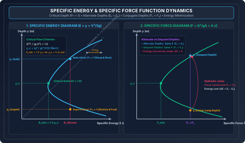
Diagram 2: Channel Transitions, Bed Humps & Choking Mechanics
+--------------------------------------------------------------------------------------------------+
| FIGURE 2: LONGITUDINAL PROFILE OF BED HUMP & WIDTH CONTRACTION CHOKING PHENOMENA                 |
+--------------------------------------------------------------------------------------------------+
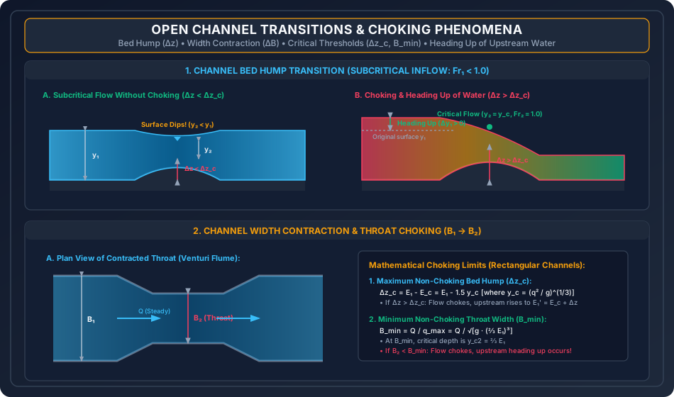
The schematic below details the physical mechanisms of flow past a bed hump () and through a contracted flume (), delineating the unchoked regime from the choked regime with upstream water heading-up.
6. Comparative Engineering Analysis & Parameter Regimes
Table 6.1: Critical Depth and Minimum Specific Energy Formulas by Section Shape
| Cross-Section Geometry | Top Width | Flow Area | Critical Flow Condition () | Critical Depth Formula () | Minimum Specific Energy () |
|---|---|---|---|---|---|
| Rectangular (Width ) | |||||
| Triangular (Side slope ) | |||||
| Parabolic () | |||||
| Trapezoidal (, slope ) | Implicit: Solved via Newton-Raphson | ||||
| Circular (Diameter ) | Transcendental / Design Tables | Evaluated at |
Table 6.2: Alternate Depths vs Conjugate (Sequent) Depths
| Comparison Parameter | Alternate Depths () | Conjugate / Sequent Depths () |
|---|---|---|
| Governing Physical Curve | Specific Energy Curve () | Specific Force Curve () |
| Conserved Quantity | Specific Energy is Constant () | Specific Force is Constant () |
| Energy Dissipation () | Zero Energy Loss () | Significant Energy Loss () |
| Physical Manifestation | Seamless frictionless channel transition (e.g., hump or contraction). | Rapidly varied turbulent flow (Hydraulic Jump). |
| Mathematical Equation | ||
| Roots on Curve | One subcritical and one supercritical depth at same . | One supercritical and one subcritical depth at same . |
7. Worked Numerical Examples (Pre-Calculated & Verified)
Problem 1: Critical Depth, Froude Number & Alternate Depths
Problem Statement: A rectangular flume of width carries a steady discharge .
- Calculate the discharge per unit width , critical depth , critical velocity , and minimum specific energy .
- If the observed depth of flow is , determine the flow regime (subcritical or supercritical), Froude number , and specific energy .
- Compute the alternate depth that possesses the exact same specific energy .
Step-by-Step Solution:
-
Critical Parameters:
-
Flow State at :
-
Alternate Depth Computation ():
Multiply by :
Since is already a known root, factor out :
Solve the quadratic equation for the positive supercritical alternate root:
Check Velocity & Froude number of alternate state:
Problem 2: Bed Hump Transition & Choking Calculations
Problem Statement: In the rectangular channel of Problem 1 ():
- Determine the maximum allowable height of a smooth upward bed hump without causing choking or modifying upstream flow conditions.
- If a hump of height is installed, calculate the depth of flow over the hump crest and the net drop in the free water surface elevation.
- If a hump of height is installed, prove that choking occurs. Calculate the resulting flow depth at the hump crest, the new elevated upstream depth , and the total heading-up of water.
Step-by-Step Solution:
-
Critical Bed Hump Height ():
-
Case A: (No Choking):
Since , the flow remains subcritical over the hump:
Solving for the subcritical root via Newton-Raphson iteration:
Water surface elevation above datum:
-
Case B: (Severe Choking!): Because , the flow over the hump crest is forced to the critical state:
The upstream flow cannot remain at . Energy required at Section 1:
Determine the new subcritical upstream depth :
Solving for the subcritical root ():
New upstream velocity: .
Problem 3: Width Contraction & Triangular Critical Flow
Problem Statement:
- Part A (Venturi Flume Contraction): For the rectangular channel in Problem 1 (), determine the minimum throat width without choking. If the channel is contracted to , find the depth of flow at the throat .
- Part B (Triangular Critical Channel): A symmetric triangular canal has side slopes () and conveys a discharge . Compute the critical depth , critical top width , critical velocity , and minimum specific energy . If the upstream depth is , find the Froude number and specific energy .
Step-by-Step Solution:
Part A: Rectangular Width Contraction:
- At the critical contraction width , the throat depth is :
- Maximum discharge per unit width at the throat:
- Minimum non-choking throat width:
- Flow at (No choking): Solving for the subcritical root:
Part B: Triangular Channel Critical Dynamics:
- Side slope :
- Geometric dimensions at critical state:
- Critical velocity & Minimum Specific Energy: Check Froude number:
- Flow at :
8. High-Yield Examination Traps & Ambiguities
[!WARNING]
Trap 1: Subcritical vs Supercritical Water Surface Response to a Bed Hump
Students frequently assume that an upward bed hump always pushes the water surface upward. This is only true for supercritical flow!
- Subcritical Flow (): Water depth decreases, and the water surface dips downward!
- Supercritical Flow (): Water depth increases, and the water surface rises upward!
[!WARNING]
Trap 2: Minimum Specific Energy Multipliers ( vs )
Do not use indiscriminately across all channel shapes:
- Rectangular Channel:
- Triangular Channel:
- Parabolic Channel: In competitive exams, questions about triangular flumes frequently trap students who multiply by instead of .
[!WARNING]
Trap 3: Confusing Alternate Depths with Sequent Depths
- Alternate Depths: Lie on the same Specific Energy curve (). They represent frictionless flow with zero head loss.
- Sequent (Conjugate) Depths: Lie on the same Specific Force curve (). They represent flow across a hydraulic jump, where substantial energy is irreversibly dissipated as turbulent heat ().
[!CAUTION]
Trap 4: Choking Heading-Up Calculations
When a channel is choked by a hump , the new upstream depth cannot be computed using the old upstream energy . Students often fail to recognize that the new upstream energy is , which must be solved anew via the cubic specific energy relation.
9. Real-World Engineering Applications & Case Studies
9.1 Broad-Crested Weirs & Venturi Flumes as Flow Meters
Critical flow dynamics forms the operational foundation of primary open channel flow meters:
- Broad-Crested Weir: A raised rectangular platform installed across a canal functions as a controlled bed hump designed to deliberately exceed . Flow over the crest is forced into the critical state (). By measuring only the upstream head , the discharge is uniquely determined without needing velocity measurements:
- Parshall Flume: Utilizes a combined width contraction and a downward sloping bed dip to establish critical flow at the throat, providing highly accurate, self-cleaning discharge metering with minimal head loss for irrigation canals and wastewater plants.
9.2 Culvert Inlet Control & Roadway Overtopping
Highway culverts frequently operate under "Inlet Control", where the culvert barrel can carry more discharge than the inlet geometry allows. The inlet acts as a contracted transition where critical depth forms immediately inside the entrance. If storm discharge increases beyond design capacity, choking occurs at the inlet, causing water to back up and overtop the highway embankment.
10. Cross-Disciplinary & Downstream Dependencies
                                    +-------------------------------------------------------------+
                                    |                 OCF-02: CRITICAL FLOW & ENERGY              |
                                    |       Specific Energy (E), Transitions, Choking, Fr = 1     |
                                    +-------------------------------------------------------------+
                                                                   |
                                  +--------------------------------+--------------------------------+
                                  |                                                                 |
                                  v                                                                 v
+-----------------------------------------------------+   +-----------------------------------------------------+
|         OCF-03: GRADUALLY VARIED FLOW (GVF)         |   |         OCF-04: RAPIDLY VARIED FLOW (RVF)           |
|   Bed Slope Classification (Mild: y0 > yc,          |   |   Hydraulic Jump Sequent Depths (Belanger),         |
|   Steep: y0 < yc, Critical: y0 = yc), Surface Curves|   |   Momentum Specific Force Balance (F1 = F2)         |
+-----------------------------------------------------+   +-----------------------------------------------------+
                                                                   |
                                                                   v
                                                  +-----------------------------------------------------+
                                                  |        IRRI-03: SPILLWAYS & STILLING BASINS         |
                                                  |   Ogee Spillway Crest (Fr = 1), Energy Dissipators  |
                                                  +-----------------------------------------------------+
- Downstream Module
OCF-03: Channel slopes are universally categorized by comparing normal depth (fromOCF-01) to critical depth (fromOCF-02): Mild (), Steep (), Critical (), Horizontal (), and Adverse (). - Downstream Module
OCF-04: Uses the specific force function established here to derive the classical Belanger momentum equation for hydraulic jumps.
11. Summary Formula Cheat Sheet & Memory Anchors
| Entity | Primary Formula | Examination Mnemonic / Rule |
|---|---|---|
| Specific Energy | Head referenced to channel bed | |
| Critical Flow (General) | Top width over area cubed | |
| (Rectangular) | Cube root of | |
| (Rectangular) | Energy is of depth | |
| (Triangular) | Fifth root formula | |
| (Triangular) | Energy is of depth | |
| Critical Hump () | Available energy minus minimum | |
| Choked Energy () | Critical energy plus hump | |
| Minimum Throat Width | Maximum discharge density | |
| Specific Force () | Momentum flux plus centroid pressure |
12. Comprehensive References & Standard Codes
- Subramanya, K. (2019). Flow in Open Channels, 5th Edition, McGraw-Hill Education, New Delhi. (Chapters 2 & 3: Energy-Depth Relationships).
- Chow, Ven Te (1959). Open-Channel Hydraulics, McGraw-Hill Book Company, New York. (Classic Reference for Transitions & Critical State).
- Henderson, F. M. (1966). Open Channel Flow, Macmillan Publishing, New York.
- Bakhmeteff, B. A. (1932). Hydraulics of Open Channels, McGraw-Hill, New York. (Original formulation of specific energy).
- Bureau of Indian Standards (BIS):
- IS 6062: 1971 — Method of Measurement of Flow of Water in Open Channels using Standing Wave Flumes and Venturi Flumes.
- IS 6063: 1971 — Method of Measurement of Flow of Water in Open Channels using Broad-Crested Weirs.
- IS 13083: 1991 — Open Channel Flow Measurement using Parshall and Saniiri Flumes.