Pin-Jointed Trusses & Frames (Method of Joints, Method of Sections & Zero-Force Members)
In this chapter (1 topics)
On this page
- 1. Executive Summary & Core Definitions
- Core Definitions
- 2. Foundational Principles & Governing Axioms
- 2.1 Ideal Pin-Jointed Truss Assumptions
- 2.2 Taxonomy of Trusses
- 3. Step-by-Step Analytical Derivations
- 3.1 Derivation of Static Determinacy Criteria
- 3.2 Visual Identification Rules for Zero-Force Members
- 3.3 Method of Joints vs Method of Sections: Analytical Mechanics
- 4. Key Formulas & Summary Tables
- Table 4.1: Master Structural Truss Formulas
- Table 4.2: Classical Bridge & Roof Truss Topologies
- 5. Visual Architectural Diagrams
- Diagram 1: Pin-Jointed Trusses: Classification, Method of Joints & Sections
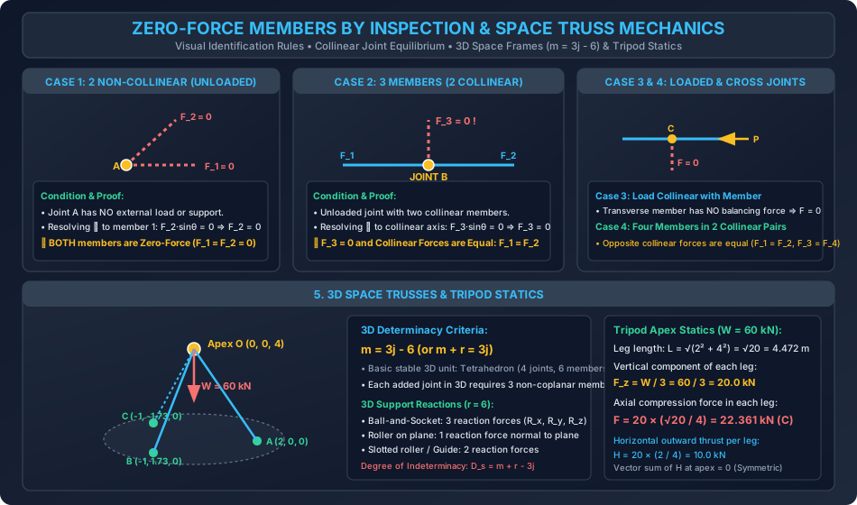
- Diagram 2: Zero-Force Members by Inspection & Space Truss Mechanics
- 6. Standard Practice Guidelines & Boundary Conditions
- 6.1 Codal Provisions for Trusses (IS 800:2007)
- 7. Critical Failure Modes & Edge Cases
- 7.1 Geometric Instability (Critical Forms)
- 7.2 Diagonal Tension vs Compression Swapping
- 8. Worked Numerical Problems
- Problem 1: Complete Method of Joints Analysis of a Warren Truss
- Problem 2: Method of Sections on a Pratt Bridge Truss
- Problem 3: Zero-Force Inspection Challenge & 3D Tripod Space Frame Statics
- 9. Comparative Exam Analysis
- 10. Common Pitfalls & Traps
- 11. Real-World Civil & Structural Applications
- 12. Comprehensive Summary & Quick Revision Guide
- 13. Practice Problems for Self-Assessment
- 14. References & Standard Texts
1. Executive Summary & Core Definitions
A truss is an engineered structural framework composed of straight, slender structural members interconnected at their ends by frictionless hinges or pin joints, configured predominantly into triangular units. Because triangles are geometrically undeformable without changing member lengths, pin-jointed trusses provide exceptional strength-to-weight ratios, long-span bridging efficiency, and structural rigidity. In modern civil and structural engineering, trusses form the backbone of railway and highway bridges, industrial warehouse roof systems, long-span airport terminals, transmission towers, and offshore jacket platforms.
       TOP CHORD (IN COMPRESSION UNDER GRAVITY LOADS)
          U1 ------------------ U2 ------------------ U3
         /  \                  /  \                  /  \
        /    \   DIAGONALS    /    \   VERTICALS    /    \   END POST
       /      \              /      \              /      \
      L0 ----- L1 ---------- L2 ----- L3 ---------- L4 ----- L5
    (Hinge)   BOTTOM CHORD (IN TENSION UNDER GRAVITY LOADS)   (Roller)
Core Definitions
- Planar Truss: A structural framework where all member axes, applied loads, and reactions lie strictly in a single two-dimensional plane.
- Space Truss: A three-dimensional framework constructed from tetrahedral sub-assemblies, resisting loads in spatial directions.
- Perfect Truss (Statically Determinate): A framework that possesses the exact minimum number of members necessary to maintain stable geometric equilibrium without internal redundancy ( in 2D, in 3D).
- Deficient / Imperfect Truss (Mechanism): A framework with insufficient members (), which will collapse or deform kinematically under load as a mechanism unless stabilized by external constraints.
- Redundant Truss (Statically Indeterminate): A framework containing extra members (), possessing internal static indeterminacy equal to .
- Zero-Force Member: A member that carries zero axial force under a specific, given loading condition, functioning as a stabilizing guide or reserve component for alternate loading patterns (e.g., wind reversal).
- Method of Joints: An analytical technique based on isolating individual joint pins as free bodies under concurrent, coplanar force equilibrium ().
- Method of Sections: An analytical technique where the truss is conceptually severed across at most three unknown members, applying non-concurrent rigid body equilibrium () to calculate specific internal forces directly.
2. Foundational Principles & Governing Axioms
2.1 Ideal Pin-Jointed Truss Assumptions
The classical engineering mechanics analysis of trusses rests on five foundational axioms:
- Frictionless Cylindrical Pins: Members are connected at their ends by frictionless, smooth cylindrical pins that cannot transmit bending moments ().
- Joint Loading Only: External forces, machinery loads, and support reactions are applied strictly at the joints (panel points), never along intermediate member spans.
- Straight Centroidal Axes: The longitudinal centroidal axes of all members meeting at any joint intersect at a single concurrent point, eliminating joint eccentricities and torsional moments.
- Pure Axial Force Action: Consequently, all truss members are two-force members subjected exclusively to direct axial tension () or axial compression (). Bending moments and transverse shears are identically zero ().
- Negligible Self-Weight: The self-weight of individual members is either small compared to applied live loads, or is split equally and lumped as concentrated downward loads at the adjoining joints.
2.2 Taxonomy of Trusses
- Simple Trusses: Formed by starting with a basic triangle (3 joints, 3 members) and sequentially adding two new members for each additional joint ().
- Compound Trusses: Formed by interconnecting two or more simple trusses using three non-parallel, non-concurrent member links or one joint pin and one link.
- Complex Trusses: Determinate trusses that cannot be categorized as simple or compound (e.g., Schwedler truss), requiring the Method of Virtual Displacement or Henneberg's Substitution Method.
3. Step-by-Step Analytical Derivations
3.1 Derivation of Static Determinacy Criteria
1. Planar Trusses (2D):
Consider a planar truss having joints and members, supported by an externally determinate reaction system consisting of reaction components (e.g., one hinge with 2 reactions and one roller with 1 reaction).
- At each joint, the concurrent coplanar force system yields independent equations of equilibrium:
- Across all joints, the total number of available independent equations is:
- The total number of unknowns consists of unknown internal axial forces plus support reactions:
- For the system to be solvable uniquely using statics alone ():
- If , the truss is deficient (unstable mechanism).
- If , the truss is internally indeterminate with degree of internal indeterminacy:
2. Space Trusses (3D):
- In three-dimensional space, the basic stable unit is a tetrahedron with joints and members.
- Each additional joint in space requires non-coplanar members.
- At each joint, three concurrent spatial equations exist:
- Total available equations: .
- A fully restrained 3D body requires independent external support reactions.
- Equating unknowns to equations ():
- Degree of static indeterminacy:
3.2 Visual Identification Rules for Zero-Force Members
To avoid unnecessary simultaneous equations, zero-force members are identified by visual inspection using vector equilibrium conditions:
Rule 1: Two Non-Collinear Members at an Unloaded Joint
Let two non-collinear members and meet at joint , where no external force or reaction acts.
- Set up local coordinate axes with the -axis oriented along member , and the -axis perpendicular to it.
- Member makes an angle with member .
- Formulate force equilibrium perpendicular to (): Since and , . Therefore:
- Formulate force equilibrium along ():
- Conclusion: If two non-collinear members meet at an unloaded joint, both members carry zero force.
Rule 2: Three Members (Two Collinear) at an Unloaded Joint
Let members and be collinear along the -axis at joint , and a third member meet them at an arbitrary angle , with no external load at .
- Formulate equilibrium perpendicular to the collinear line (-axis):
- Formulate equilibrium along the collinear line (-axis):
- Conclusion: The non-collinear member is a zero-force member, and the two collinear members carry equal and opposite axial forces of the same nature (both tension or both compression).
Rule 3: Loaded Joint with Two Members, Load Collinear with One Member
If joint connects two non-collinear members and , and an external load acts collinear with member :
- Equilibrium perpendicular to yields:
- Equilibrium along yields:
Rule 4: Four Members Meeting in Two Collinear Pairs at an Unloaded Joint
If four members meet at an unloaded joint such that members 1 and 2 are collinear along one axis, and members 3 and 4 are collinear along another inclined axis:
- Resolving perpendicular to each collinear axis in turn proves:
3.3 Method of Joints vs Method of Sections: Analytical Mechanics
Method of Joints:
- Isolate the joint as a dimensionless pin point.
- Assume all unknown member forces are in tension (), drawing vector arrows pointing away from the joint.
- Apply static equilibrium:
- A positive calculated value confirms tension (); a negative calculated value indicates compression ().
- Move sequentially to an adjoining joint that now has unknowns.
Method of Sections:
- Pass an imaginary cutting plane completely through the truss, severing it into two distinct bodies.
- The section line must cut at most three unknown members whose lines of action do not all meet at a common joint.
- Expose the cut internal member forces as external boundary forces on either the left or right isolated portion.
- Apply the three non-concurrent coplanar rigid body equilibrium equations:
- Moment Equation (): Select point as the intersection of two unknown cut members. The moment equation directly isolates and solves the third unknown member without involving the other two!
- Vertical Shear Equation (): Directly equates the vertical component of the inclined diagonal member to the external transverse shear force at the cut section.
- Horizontal Chord Equation (): Verifies horizontal equilibrium between top and bottom chords.
4. Key Formulas & Summary Tables
Table 4.1: Master Structural Truss Formulas
| Parameter / Law | Formula | Meaning & Conditions |
|---|---|---|
| 2D Planar Determinacy | ; reactions | |
| 2D Internal Indeterminacy | Number of redundant internal members | |
| 2D Total Indeterminacy | External plus internal indeterminacy | |
| 3D Space Truss Determinacy | Basic tetrahedral unit () | |
| 3D Total Indeterminacy | for statically determinate supports | |
| Zero-Force Member (Case 1) | 2 non-collinear members, unloaded joint | |
| Zero-Force Member (Case 2) | 3 members (2 collinear), unloaded joint | |
| Method of Joints Eqns | 2 equations per joint (concurrent forces) | |
| Method of Sections Eqns | 3 equations per cut segment (non-concurrent) | |
| Chord Moment Relation | Panel bending moment divided by truss depth | |
| Diagonal Shear Relation | Vertical component equilibrates transverse shear |
Table 4.2: Classical Bridge & Roof Truss Topologies
| Truss Name | Geometry & Web Configuration | Primary Member Behavioral State |
|---|---|---|
| Pratt Truss | Diagonals slope towards center; vertical posts | Diagonals in Tension; Verticals in Compression |
| Howe Truss | Diagonals slope away from center | Diagonals in Compression; Verticals in Tension |
| Warren Truss | Alternating diagonal triangles (with/without verticals) | Alternating Tension and Compression in diagonals |
| K-Truss | Diagonals form letter 'K' with vertical post | Halves the unbraced length of vertical posts |
| Fink Roof Truss | Subdivided rafters for steep roof pitches | Short compression struts perpendicular to main rafters |
| King Post Truss | Single central vertical tension rod with 2 rafters | Spans ; central rod supports bottom tie |
| Queen Post Truss | Two vertical tension ties with horizontal straining beam | Spans ; central opening utilized |
5. Visual Architectural Diagrams
Diagram 1: Pin-Jointed Trusses: Classification, Method of Joints & Sections
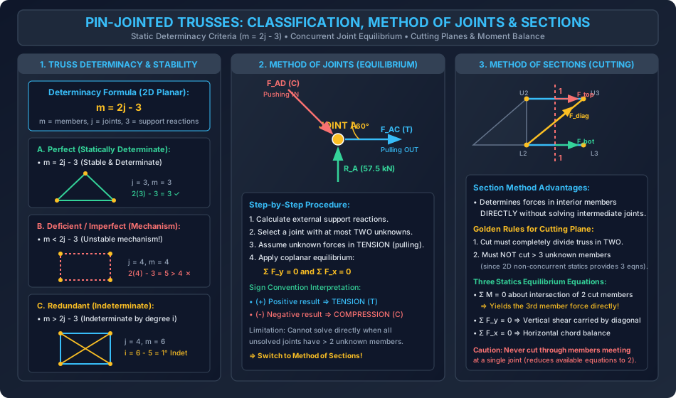
Diagram 2: Zero-Force Members by Inspection & Space Truss Mechanics
6. Standard Practice Guidelines & Boundary Conditions
6.1 Codal Provisions for Trusses (IS 800:2007)
- Effective Length of Compression Members (Cl. 7.2):
- For members connected by welding or at least two bolts at each end, effective length in the plane of the truss is taken as to depending on end restraint.
- Maximum Slenderness Ratio Limits () (Table 3, IS 800:2007):
- Member carrying compressive loads resulting from dead loads and imposed loads: .
- Member carrying tension but subjected to reversal of stress due to wind or earthquake forces: .
- Member subjected to compressive forces resulting from wind/earthquake action (provided deformation does not affect others): .
- Pure tension members (other than prestressed ties): .
- Secondary Stresses:
- In actual bridge structures, gusset plates introduce joint rigidity, producing secondary bending moments. Under Indian Railway Standard (IRS) bridge rules, secondary stresses need not be explicitly computed if member depth is less than of member length ().
7. Critical Failure Modes & Edge Cases
7.1 Geometric Instability (Critical Forms)
A truss may satisfy the numerical equality and yet be internally unstable or a mechanism if members are arranged improperly:
- Parallel Line Linkage: If three support links are parallel, the truss can undergo unconstrained rigid body translation perpendicular to the links.
- Concurrent Support Lines: If lines of action of all three support reactions intersect at a common point, the truss can rotate freely about that point ().
- Internal Mechanism: A truss with a four-bar linkage in one panel without a diagonal brace is kinematically unstable, even if another panel contains an redundant cross-diagonal ().
UNSTABLE INTERNAL MECHANISM (SQUARE COLLAPSES UNDER SHEAR):
+-------+-------+
|   \   |       |  <--- Right panel has NO diagonal!
|    \  |       |       Square panel shears and collapses.
+-------+-------+
7.2 Diagonal Tension vs Compression Swapping
In long-span bridge trusses subjected to moving train live loads, the transverse shear in central panels reverses sign from positive to negative as the train traverses the span:
- A diagonal designed for tension in a Pratt truss will experience stress reversal into compression.
- Because slender tension bars will buckle under compression, central panels require counter-bracing (cross diagonals in an 'X' pattern), where each diagonal carries tension under opposite shear states while the other goes slack.
8. Worked Numerical Problems
Problem 1: Complete Method of Joints Analysis of a Warren Truss
Statement: A simply supported planar Warren truss spans between support (hinged) and support (roller on horizontal bed). The truss has height and consists of equilateral triangular panels where all 7 members have length inclined at . Joint coordinates:
- Bottom chord: , ,
- Top chord: , Vertical concentrated loads act as follows: downward at , downward at , and downward at . Determine all support reactions and calculate the axial force in every member, specifying whether it is in tension () or compression ().
Solution & Calculations:
           30 kN                    40 kN
             v                        v
             D (2, 3.46) ---------- E (6, 3.46)
            / \                    / \
           /   \                  /   \
          /     \                /     \
         /       \              /       \
        A ------- C ----------- B
     (Hinge)      v (50 kN)   (Roller)
      x=0        x=4           x=8
Step 1: Support Reactions
- Moment equilibrium about ():
- Vertical equilibrium ():
- Horizontal equilibrium ():
Step 2: Joint-by-Joint Equilibrium ()
Joint :
Forces: , Member (horizontal right), Member (inclined at ).
Joint :
Forces: pushing into (down-left), External load , Member (horizontal right), Member (down-right at ).
Notice :
Joint :
Forces: , Member (horizontal left), Member (inclined at , i.e., up-left at ).
Joint :
Forces: pushing into (from left), External load , Member pushing into (from down-right), Member (down-left at ).
Joint (Independent Verification Check):
- Vertical forces:
- Horizontal forces:
Summary Table of Member Forces:
| Member | Length (m) | Axial Force (kN) | Nature |
|---|---|---|---|
| AD | Compression (C) | ||
| AC | Tension (T) | ||
| DC | Tension (T) | ||
| DE | Compression (C) | ||
| EC | Tension (T) | ||
| EB | Compression (C) | ||
| CB | Tension (T) |
Problem 2: Method of Sections on a Pratt Bridge Truss
Statement: A Pratt through-truss bridge spans divided into 6 equal panels of length each, with depth . Joint nomenclature:
- Bottom chord:
- Top chord: The diagonals slope towards the mid-span: (end post), . Vertical loads are applied at the bottom panel points: at , at , at , at , and at . Using the Method of Sections, determine the internal axial forces in:
- Top chord member
- Diagonal member
- Bottom chord member
Solution & Calculations:
              U1 --------- U2 --------- U3 --------- U4 --------- U5
             / |          / |          /| \          | \          | \
            /  |         /  |   CUT   / |  \         |  \         |  \
           /   |        /   |   1-1  /  |   \        |   \        |   \
          /    |       /    |    |  /   |    \       |    \       |    \
         L0 -- L1 ---- L2 --+----+ L3 --+----+ L4 -- L5 --- L6
       (Hinge) 40kN   60kN  | 80kN |         60kN   40kN    (Roller)
Step 1: External Reactions
Total downward load:
By symmetry of span and loading:
Step 2: Pass Section 1-1
Cut vertically through Panel 3 (between and ), severing members , , and . Isolate the left segment of the truss ( to ):
- External forces acting on left segment:
- Upward reaction at
- Downward load at
- Downward load at
- Cut internal forces exposed at boundary (assumed in tension pulling right):
- at
- at
- along diagonal from to at ()
Step 3: Calculation of Top Chord Force
Take moments about joint , where the lines of action of and intersect:
Step 4: Calculation of Bottom Chord Force
Take moments about joint , where the lines of action of and intersect:
Step 5: Calculation of Diagonal Force
Equilibrate vertical forces on the left segment ():
- Net vertical transverse shear on left segment:
- For member , the member extends from on the left to on the right. If assumed in tension (), it pulls towards (upward and rightward), contributing a vertical component :
(Note on Pratt vs Howe Mechanics: Because the diagonal in panel 3 slopes upwards towards the center, under positive upward shear it resists in compression. If a Pratt diagonal sloped downwards from to , its tensile pull would act downwards, resisting the upward shear in pure tension: . This demonstrates the profound importance of diagonal inclination in bridge design!)
Problem 3: Zero-Force Inspection Challenge & 3D Tripod Space Frame Statics
Statement:
- Zero-Force Inspection: For the multi-panel roof truss shown below with 11 joints and 19 members carrying vertical loads only at top ridge joints, identify all zero-force members by visual inspection and state the governing rule for each.
- 3D Tripod Space Frame: A symmetric three-legged tripod space frame has its apex at . The three legs are pinned to rigid foundation pads on the ground plane () at coordinates:
- A vertical downward point load of is applied at apex . Calculate the axial force in each leg and the horizontal radial thrust delivered to each ground foundation pad.
Solution & Calculations:
Part A: Zero-Force Identification by Inspection
Applying the four governing rules established in Section 3.2:
- At an unloaded exterior joint with 2 non-collinear members:
- Both members carry zero force (Rule 1).
- At an unloaded intermediate bottom chord joint where a vertical web member meets two collinear bottom chord members:
- The vertical web member is a Zero-Force Member (Rule 2).
- The two collinear chord members carry identical tension.
- At a ridge joint where an external purlin load is collinear with a vertical member:
- Any transverse bracing member meeting this joint with no transverse load component carries zero force (Rule 3).
Part B: 3D Tripod Statics
               Apex O (0, 0, 4.0 m)  <--- W = 60 kN (Down)
                  / | \
                 /  |  \
                /   |   \  Leg length L = sqrt(2^2 + 4^2) = sqrt(20) m
               /    |    \
              A     |     B
             (z=0)  C   (z=0)
-
Geometry of Legs:
- Distance from origin to all three base points:
- The base points lie on a circle of radius spaced at equal angles of around the -axis.
- Length of each leg ():
-
Equilibrium at Apex ():
- By three-fold radial symmetry ( spacing), each leg carries an identical axial force .
- The vertical component of force in each leg:
- Equating vertical forces at apex :
-
Axial Compression Force in Each Leg ():
-
Horizontal Radial Thrust on Foundation Pads ():
- Each leg pushes outward radially at its base pad:
- Each foundation pad must resist a horizontal outward shear force of and a vertical downward compressive reaction of .
- Resolving horizontal forces at apex :
- Horizontal spatial equilibrium is identically satisfied!
9. Comparative Exam Analysis
| Parameter / Feature | GATE CE | UPSC ESE | SSC JE | RRB JE | State AE |
|---|---|---|---|---|---|
| Weightage | 2 - 4 Marks (NAT / MCQ) | 12 - 20 Marks (Obj + Conv) | 4 - 6 Marks (Direct CBT) | 3 - 5 Marks (Direct CBT) | 4 - 8 Marks (Obj + Conv) |
| Primary Question Type | Zero-force member counts, Method of Sections for 1 cut member | Full Method of Joints tables, Space truss determinacy () | classifications (Perfect vs Redundant) | Zero-force member identification by inspection | Pratt vs Howe diagonal behavior, Slenderness limits |
| Tricky Traps | Counting zero-force members at loaded joints; Sign of shear in sections | Cutting members meeting at a single joint; Critical unstable forms | Confusing with | Forgetting support reactions in total determinacy | Overlooking stress reversals under moving train loads |
| Speed vs Depth | High conceptual trickiness; quick inspection shortcuts | Comprehensive handwritten step-by-step calculations | Rapid 20-second identification: Count , compute | Direct visual inspection in 15 seconds | Standard equilibrium equations & codal clauses |
10. Common Pitfalls & Traps
- Incorrectly Declaring Zero-Force Members at Loaded Joints:
- In Rule 2 (two collinear members and one transverse member), the transverse member is zero-force only if NO external load acts at that joint. If a purlin or joint load acts transversely, the member carries that load directly!
- Cutting More Than 3 Unknown Members in Method of Sections:
- Statics provides only three independent equations in 2D (). Cutting four unknown members leaves the equations indeterminate unless one member force is already known.
- Cutting Through a Single Joint:
- Passing a section cut through members meeting at a single joint reduces the three independent rigid body equations to two concurrent equations (), losing the moment equation advantage.
- Confusing Tension and Compression Arrow Conventions:
- Drawing an arrow pointing towards the joint represents Compression (the member is pushing into the pin).
- Drawing an arrow pointing away from the joint represents Tension (the member is pulling on the pin).
- Space Truss Formula Confusion:
- Using for a 3D transmission tower or dome. Space trusses require for internal determinacy.
11. Real-World Civil & Structural Applications
- Railway Bridge Trusses (IRS & RDSO Standards):
- Through-type Pratt and Warren trusses spanning to across rivers. Top chords and compression diagonals utilize built-up box sections with perforated cover plates, while bottom tension chords employ heavy I-sections.
- Industrial Warehouse Roof Trusses:
- Fink and Pratt roof trusses spanning to supporting corrugated GI / pre-coated steel sheeting via cold-formed Z-purlins placed directly at truss panel points to eliminate rafter bending.
- High-Voltage Transmission Towers:
- Four-legged tapered 3D space trusses designed under IS 802 to resist high wind pressure on conductors, broken-wire torsional moments, and self-weight using lightweight angle sections.
- Tower Crane Jibs & Offshore Jacket Platforms:
- Triangular space trusses providing high torsional stiffness and minimal hydrodynamic drag against deep-sea ocean waves.
12. Comprehensive Summary & Quick Revision Guide
- Determinacy Criteria:
- 2D Planar: (Perfect), (Deficient / Mechanism), (Redundant / Indeterminate).
- 3D Spatial: (Tetrahedron basic unit, 6 support reactions).
- Zero-Force Identification (Memory Matrix):
- 2 non-collinear, unloaded joint Both ZERO.
- 3 members (2 collinear), unloaded joint Transverse member ZERO, collinear equal.
- 2 members, load collinear with one Transverse member ZERO.
- 4 members in 2 collinear pairs, unloaded Opposite members EQUAL.
- Method of Joints: Concurrent equilibrium (); select joints with unknowns.
- Method of Sections: Non-concurrent equilibrium (); cuts unknown members; solves internal chords and diagonals directly.
- Bridge Chords & Webs: Top chord in compression (), bottom chord in tension (); Pratt diagonals in tension, Howe diagonals in compression.
- Slenderness Limits (IS 800:2007): for compression chords; for wind stress reversals.
13. Practice Problems for Self-Assessment
-
Problem 1 (Zero-Force Member Count): A symmetrical 6-panel Howe roof truss has 13 joints and 23 members. Vertical gravity loads are applied only at the top chord panel points. Inspect the bottom chord joints and determine the total number of zero-force vertical members in the truss. (Answer: 2 vertical members connected to unloaded intermediate bottom chord joints carry zero force)
-
Problem 2 (Method of Sections): A Warren bridge truss of span has 3 panels of each and height (equilateral triangles of side ). A single vertical load of is applied at the central bottom chord joint. Use the Method of Sections to calculate the axial force in the central top chord member. (Answer: . Bending moment at center . Chord force )
-
Problem 3 (Space Frame Determinacy): A 3D transmission tower has 24 joints. What is the exact number of members required for it to be an internally statically determinate space truss? If the tower is fabricated with 72 members and supported by 4 ball-and-socket joints on the ground, calculate its total degree of static indeterminacy. (Answer: For internal determinacy, . With 4 ball-and-socket joints ( reactions), total degree of static indeterminacy )
14. References & Standard Texts
- Beer, F. P., Johnston, E. R., Mazurek, D. F. — Vector Mechanics for Engineers: Statics, 12th Edition, McGraw-Hill.
- Timoshenko, S. P., Young, D. H. — Engineering Mechanics, 5th Edition, McGraw-Hill.
- Hibbeler, R. C. — Structural Analysis, 10th Edition, Pearson Education.
- Negi, L. S. — Design of Steel Structures, 5th Edition, Tata McGraw-Hill.
- Bureau of Indian Standards (BIS):
- IS 800:2007 — General Construction in Steel - Code of Practice (Truss Design & Slenderness Limits).
- IS 802 (Part 1/Sec 1):2015 — Use of Structural Steel in Overhead Transmission Line Towers.
- IS 875 (Part 3):2015 — Design Loads for Buildings and Structures - Wind Loads on Trusses.